Valve Adjustment Kawasaki ZX6E How to, DIY, Step by Step Instructions
Hi all. Here are step by step instructions with pics for how to check your valve clearances and adjust them. I just finished this job. I also have a video for it as well.
Video of adjusting valves I made, click here:
Tools: Ratchet, 10mm, 12mm, 8mm, 14mm, 19mm sockets, ratchet drive extension, needle nose pliers or regular pliers if you don’t have that, phillips screwdriver, flathead screwdriver, feeler gauges set, torque wrench is a good idea, spark plug socket or 16mm deep socket, RTV sealant or equivalent Silicon sealant for valve cover portions. A strong magnet makes this much easier. An 8mm wrench is needed if you don’t want to pull your lower fairing off. Rubber mallet is good to have on hand to whack tightened items, Razor or a way to remove gasket material. Nitrile gloves and shop towels / rags are nice to have. I will update as I recall other items.
Parts: Spark plug O rings (the manual says to replace – I didn’t), valve cover gasket – I did replace mine as it was leaking oil. Often you can reuse them if in decent shape as they are resilient rubber.
You will need 7.48mm diameter Shims – assuming you have to make any adjustments, but you cannot know what sizes until you get in there. If your spark plugs are 10,000 – 15,000 miles on them or more you might want to replace those while there. NGK CR9E is the proper part for spark plugs.
There is a lot here on this post. It may look intimidating, but it’s not too difficult and much of it becomes very obvious when you are in there looking at it all.
Get started!
Bike must be stone cold, so it should have sat overnight without the motor running.
-Remove seat.
-Disconnect negative battery terminal
-Remove left rear fairing
-Remove fuel tank (disconnect one main fuel line, and disconnect fuel gauge wire). I learned a new trick here – use a pen cap to shove into the main fuel line to seal it while working on the bike.
-You may want to remove left or both middle fairings or neither one (I later took out my left middle fairing).
-You may want to remove your lower fairing. I did not.
-Remove airbox.

-Remove left and right ram air tubes out of the frame – you will need this clearance.

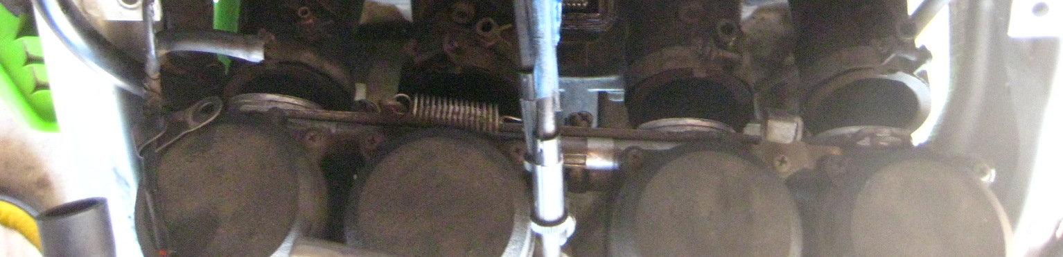
-Loosen carb mount throat band clamps and slide carbs out of engine intake boots. You can leave it just slid back, I did.
-Get any emissions tubes out of your way.
-Unplug the spark plug boots.
-Unplug ignition coil wires and move aside.
-Remove both ignition coils – unbolt their black metal mounts and take both parts out – you will need this clearance.

-I disconnected my choke cable from the carbs. Easy, you can lever the choke on, then push it back in while holding the cable to give it slack and it can come right out from the choke anchor point at the carbs.
I moved it out from the frame hole and routed it over towards the right handlebar – out of the way.


You can leave your throttle cables attached. They are a pain to re-connect so I left mine attached.
-Disconnect the motor plastic heat shield. It has two 10mm bolts that hold it in at the upper front part of the motor / valve cover area. Shove the loose heat shield as far forward and slightly up as you can (for clearance).
-Unbolt the four 8mm bolts holding in the pickup cover (middle right lower side of bike – round smaller cover in front of the clutch cover). I used a wrench on the upper front one without removing my lower fairing. Your mileage may vary. You may prefer to have easier access to bolt #4. 
-Unbolt the valve cover. It should free up where you can move it, if not very gently tap it with a rubber mallet.
How to get the valve cover out:
I shoved the main wiring loom up. I raised the right side of the cover up and diagonally pivoted the right side toward the rear of the bike and was able to finesse it out. There is very little clearance here, you will feel it hitting things below while trying to wiggle it out of there. 
Now you are looking at your valve train and camshafts and sprockets and chain.

-Back to your pickup coil area. Use a 19mm socket and turn the motor CLOCKWISE (only!) until the 1/4 T marks line up with the upper 12:30 / 1pm O’clock position raised up built in ‘indicator’. I’m pointing at indicator below:


Look at cylinder #1 area (far left of bike sitting on it). The lobes should be facing away from eachother and up slightly close to 40 degrees / 45 degrees. If they face in, or cylinder #4 lobes are facing away from eachother, you have #4 cylinder at TDC. See here how #4 cylinder is at TDC.


Rotate the crank again at the pickup coil cover area a full 360 degrees which will put #1 at TDC.

The above green arrow is pointing to the #1 lobe facing out or away from eachother. (Arrow is not directional sign).
You can now measure your valve clearances. There are 16 to check. By setting #1 cylinder at TDC you can check all (4) valves of #1 cylinder, plus the exhaust valves on #2 cylinder, and the intake valves on #3.
Insert your feeler gauges between the camshaft lobe the the inverted shiny bucket below it. I am checking cylinder #3 intake valve while #1 is at TDC:

Feeler should have a slight drag on it but if you have to force one in, it’s the wrong size. Use the smaller number in that case. Write down each measured value for each specific valve. I made a rectangular chart with EX and IN tables and 8 boxes for each valve. Write down the numbers with something like that to keep track of each one. This is very important if you need to adjust your valve clearances. You must know all this information.
There are different spec values for the EX and IN valves. Clearance specs for our bike are this range:
Exhaust (EX): .22mm – .31mm
Intake (IN): .15mm – .24mm
Rotate the crank again at the pickup coil cover area a full 360 degrees which will put #4 at TDC. You can measure the clearances of all of #4 valves, the Intake valves on #2 and the exhaust valves of #3.
(You can also spin the crank again to the 2/3 T lines and check all 4 valves on one of the #2 or #3 cylinders if you like. It’s the same idea: as long as the cylinder’s Intake and Exhaust lobes face away from eachother and slightly up you have that cylinder at TDC and can measure the valve clearances for that cylinder).
If any of the valves are out of spec you will need to swap shims to alter the clearance to within spec.
If everything is within spec pat yourself on the back, you are done. Reassemble and go ride!
However, you probably will find valves out of spec if you waited awhile like me.
To remove the camshafts and to change shims and alter your clearances:
At this point, you actually want to have #1 cylinder at TDC. Recall if the indicator is at 1/4 T mark, either #1 or #4 could be at TDC right now.The manual glosses this over point, that either #1 or #4 could be at TDC just by lining up the 1/4 T mark.
Put #1 at TDC! If it isn’t (which way are lobes on #1 pointing – inward then #4 is at TDC), so turn the crank bolt at the pickup cover another full revolution back to 1/4 timing marks. This will now put cylinder #1 at TDC (#1 lobes are facing away from eachother right?).
The reason you want #1 at TDC instead of #4 is because the timing marks are much better and easier to understand and line up on the #1 TDC marks on the camshaft sprockets. Do not move the crank again once you’ve set it to #1 TDC and have started below procedures – Important!
Now look at your camshaft sprockets.
The rear one is the Intake marked IN, and the front one is the Exhaust camshaft marked EX.
You should see the IN — line at the rear of where the valve cover meets the head and the EX — line at the front of where the cover meets. They should be evenly horizontal. Below is the IN camshaft with factory line at the cover / case split:
Now count the links and / or rivets between those horizontal marks. My bike had the timing marks in between whole links. The book mentions links split the lines. Either way, use logic / math, the two lines should have 17 links between them and 34 rivets. If your marks are like the manual, you have 16 links and (2) half links between the marks which also equals 17 links (and 34 rivets).

NOW MARK your camshafts – both, and the sprocket with a line. THIS IS VERY IMPORTANT. I have written that in ALL CAPS, like I am almost shouting. It’s that important.
Skip this, forget this, and you have made more work for yourself and stress.  Make sure to mark them well. I used a metallic sharpie and that wasn’t the best as the marks nearly wore completely off from handling the chain. Paint pen / paint is best. Mark lines across both the chain and sprocket for timing alignment marks.
-Remove the CCT (Cam Chain Tensioner). It’s located under and in front of the carbs. I’m pointing to it.

-Remove the center bolt (12mm) first. This will release an under pressure spring and pin and copper washer with the bolt. Place aside.
-Remove the two outer bolts (10mm) now and remove the CCT housing from the engine. I had to whack mine with a rubber mallet, it was stuck in there pretty good. It popped out with some energy.
Now the camshafts have what’s called caps on top of them, big machined blocks of aluminum holding them down and inline (we could abbreviate them as Al Caps, haha).
 Look closely at the 16 bolts. They have little numbers beside them.
 Start to loosen the bolts a turn at a time in the order starting at #16 to unbolt (you tighten on reinstall starting with #1).
Do Not loosen the entire bolt. Just a little at a time to start until all the pressure has been released from the camshafts. If you don’t do it this way you won’t be able to get the caps off due to pressure misalignment.
You may want to remove the spark plug O rings here. At least be careful they don’t fall off and down into the motor:


Once the caps are off – again Do Not move the crank now again until the job is nearly finished!
When you remove the camshaft caps, be mindful there are 4 locating dowels in between the camshafts. They may have come out with the caps. Make sure where all 4 are, and that they are not missing or fallen down into the motor. They also have 4 very small O rings around them. I left mine in place as is (see pics). I ALSO left these lower spark plug O rings right where they were. This is where the manual insists to replace them. Anyway, I didn’t so there you go.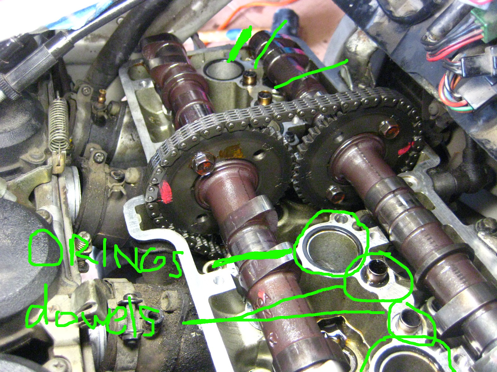
Next, You can in fact remove the camshafts without unbolting the sprockets like the manual says to do. You can move out the IN camshaft and sprocket together first and set aside.
 Have something right on hand to tie up the timing chain and keep tension on it so it does NOT come out of the teeth of the crank down below in the motor. Remove the EX camshaft and tie up the chain not letting the chain fall / drop / slacken much at all.

I used the throttle cables to tie the chain to.

With your camshafts out you have now exposed your buckets, the shiny metal round things upside down on top of your valve.


You need to remove the bucket and shim for any valve that was outside the factory spec value. You can leave in ones that are within spec. I had 14 or maybe 15 out of spec so I just pulled them all.
 The shim is stuck under the bucket in the above pic. Those shims are small! Like a small watch battery size.
I used a very strong magnet to remove them easily. With a strong magnet the shim should also come out at the same time under the bucket. Place the magnet center of the bucket for removal of bucket and shim together.
Take them out one at a time and put them in specific labeled spot for each valve. Each shim is different thickness if the valves have ever been serviced and it’s imperative to know which came from which for measuring. I used an egg carton and half dozen egg carton and marked one side IN and one side EX and put the buckets and shims in there to know which was which. 
So now you need to measure each shim that came out for any valve clearance you need to adjust and write down the precise thickness of them for each specific valve to tour table. Record final values in mm / metric as the charts are in metric as are the shim numbers for ordering.
So there are going to be a few figures for any valve clearance you want to adjust:
– Measured clearance
– Measured shim thickness
– Desired clearance
As the clearance are a range of values, you just need to get in that area. I opted for trying to make the valves all on the looser side of the spectrum as they will tighten with miles.
Then you can consult the Kawi manual lookup chart to find out what size shim you need to replace them with.

Write numbers down on paper, etc… I used a little whiteboard. The shims that are calculated to go back in are sitting on the board.
You can mix and match and replace with existing / used shims. You likely will find at this point you may have to go get certain specific shims that you need.
Basically the way this all works is, that generally the valves tighten up with mileage and the clearances lower / tighten. To get a larger clearance you need to get at thinner shim.
So if a shim that came out was measured at 3.00mm and your clearance was say around .20mm too tight for the spec you want, you would in this case replace it with a 2.80mm shim.
How about a specific example from my bike?:
On Cylinder #1 I measured my left exhaust valve at .038mm (way too tight!)
Spec for the exhaust is range of .22mm – .31mm
The shim that came out was a 2.95mm
Chart lookup value calls for a 2.70mm shim
New clearance once installed measured a .279! Perfect, the high side of the clearance range.
If you check some math there, the difference between the old and new shim 2.95mm and 2.70mm is .25mm
.25mm added to original measured clearance of .038 = .288 very close to the figure I got above. This is how it works. (in my case the .038mm feeler gauge could barely fit in between the lobe and bucket but it was the thinnest one my set came with).
You can calculate it yourself or use the chart. I used the chart to start, and then re-did all the math myself several times to make sure I was getting what I needed. I did not want to do this twice.
Once you have it all figured out (my first time – I took hours writing and calculating I think), get your new shims and install them in the proper valve spot. Then re-install your buckets. I kept my buckets stored and back in with the exact valve it came from.
Once they are all in it’s time for reassembly.
-Make sure your crank is still at 1/4 T mark.
Lubricate the bearing spots that hold the camshafts with motor oil. Or make sure they are still oily from before at least.
-Place your EX camshaft in first and line it perfectly back up with the link on the chain your mark meets up with on your sprocket. It will make this a fairly taut fit against the chain (and the crank below). That’s good.
-Install the IN camshaft next.
OK so here’s where you can toss some manual sh*t out the window. It states to have the camshafts in perfectly and flat down so that the IN — and EX — line marks are perfectly lined up with the case line and no slack on the chain. Yeah, good luck with all that. You’d need a circus strongman and or about 6 hands to shove the camshafts down on top of some resisting valve springs and hold it all perfect… plus it’s a waste of effort and time.
Think about it, the only thing that moves those sprockets is the chain which is only moved by the crank below. Even if there is some slack or not perfect lining up of the IN — mark and EX — mark on the case line, it will align itself.
JUST MAKE SURE your sprocket and chain link marks are perfectly lined up on both. You made those marks right? And that you never let pressure off your chain – and therefore let it slip off the crank sprocket deep down below.
Have the front EX camshaft tight-ish is nice (doesn’t have to be) and let the IN camshaft go where it’s going to go – it won’t be perfect. There will be chain slack between them. That’s ok, it’s all gonna fix itself.

If you removed any of the 4 locating dowel reinstall them and make sure the small O rings are around them. Also if you are replacing or removed the lower spark plug O rings, put them all back in now.
Now re-install the camshaft caps starting with #1 bolt. I tightened each one until there was resistance and then went slowly a little at a time in order #1 – #16. This will flatten down the camshafts. But don’t worry they are off yet. DO worry and make sure the chain doesn’t jump off either sprocket’s teeth.
By tightening down the caps, they will likely rotate and move around your camshafts a bit like how it happened to me below. This is ok, just Make Sure your marks are still lined up, and that there is the 17 links between the horizontal marks on the sprockets. 

-Once the caps are tightened to 12 NM (104 inch/lbs) of torque, YOU MUST reset your CCT. If you put it back in as it was you will likely break something and cause damage. Reset it.
You do that by pressing in the little button and then pushing back the little “plunger” (foot thingee) back into it’s holder. I’m pointing to the ‘button’ you depress to push the plunger back into the housing.
This pics shows the ‘plunger’ retracted after resetting it:

-Now re-install the CCT housing, the raised arrow on it aligns horizontally at the top (but not pointing ‘up’).
-Bolt in those two 10mm bolts on the housing.
-Reinstall the bolt, copper washer, pin, and spring into the CCT housing. It will be tad difficult as the spring will push back on you, but get the bolt in and tighten to 9.7 NM.
This will now engage the CCT to put pressure on the chain.
Make sure your painted on marks are all lined up and you have that 34 rivets / 17 links between the sprockets IN and EX lines.
-Now go turn the crank clockwise: Most likely you will see the slack between the sprockets go away instantly!
The chain will pull both camshafts where they need to be. Before turning crank:
After turning crank:
-Rotate the engine many revolutions to set the shims and make sure everything feels normal and sounds good. If you messed up the timing now is, well, the time to figure that out. Any major resistance stop! You may be mis timed and forcing valves into pistons.
-Now you will re-measure your valve clearances and make sure they are all within spec. If they are not – you know what you’re doing next. Figure out which ones are off, figure out the proper shim, and get it / swap it in from spares once you’ve taken the caps off again and the camshafts out. Hopefully you’ve gotten it all right and won’t have to do this (I did not have to).
If you have gotten them right – congratulations! You owe yourself a beer tonight.
So time to re-install it all.
What I did was turn the motor several times by hand to make sure it all felt right and then re-installed the pickup coil cover. I cut my own gasket for it as the old one was toast on removal.
-Then reinstall your valve cover and gasket. Make sure to use sealant on the (4) lower half moon cutout parts of the gasket – I used hi temp RTV silicone sealant. I got my cover wiggled back in less than one song on the radio – it was finesse-y but not too bad. I moved the wiring loom up a lot and slid it back in under the left side first.
-Reinstall the valve cover bolts and torque to 9.8 MM (87 inch/lbs).
-Re bolt in the black plastic heat shield
-Install the spark plugs.
-Install the coils and mounts back and the spark plug boots.
-Re connect the ignition coil wiring.
-Re install your carbs into the boots and tighten the band clamps.
-Reattach your choke cable to the carbs.
-Re-attach the negative terminal of the battery.
Now at this point I decided to test fire the bike. I had fuel still in the fuel lines and carbs so I fired it up with the tank off. It cranked a little as I had the choke in wrong position but fired right up and sounded great!
Then reassemble the rest of the bike.
-Reinstall ram air tubes.
-Reinstall airbox and then all vacuum lines and hoses.
-Reinstall the fuel tank and fairings.
Congratulations! Go ride!
This was my first I4 motorcycle valve adjustment. (I’ve done my 16 valve car before and an 6 valve inline twin Honda motorcycle – that was cake). It’s not a really difficult job, I just got agitated when I could not get any feeler gauge to go into the exhaust valves on cylinder #1 and #4 (because they had tightened to zero clearance and I did not know that yet) and a few things in the manual were not clear and an item wrong.
A weekend timeframe would be a good time estimate if this is your first time and you are somewhat handy in the garage. You likely have to factor in getting certain shims. You might be able to get this done in a day. But you will feel really good about getting it done and probably take half the time next time.
My motor sounds better, starts way better than it ever has since I’ve owned it, I have better low end power. I had 3 exhaust valves at zero, or less than .038mm anyway, clearance. I was risking burning a valve and probably had lower compression and power as a result. I was pretty thrilled to get this done.
Posted in DIY, repair and tagged adjust valves, clearances, DIY, DOHC, how to, i4, inline four, Kawasaki, Ninja, Valve adjustment, valve clearances, Zx6e, zzr600 by green