Valve Adjustment Kawasaki ZX6E How to, DIY, Step by Step Instructions
Hi all. Here are step by step instructions with pics for how to check your valve clearances and adjust them. I just finished this job. I also have a video for it as well.
Video of adjusting valves I made, click here:
Tools: Ratchet, 10mm, 12mm, 8mm, 14mm, 19mm sockets, ratchet drive extension, needle nose pliers or regular pliers if you don’t have that, phillips screwdriver, flathead screwdriver, feeler gauges set, torque wrench is a good idea, spark plug socket or 16mm deep socket, RTV sealant or equivalent Silicon sealant for valve cover portions. A strong magnet makes this much easier. An 8mm wrench is needed if you don’t want to pull your lower fairing off. Rubber mallet is good to have on hand to whack tightened items, Razor or a way to remove gasket material. Nitrile gloves and shop towels / rags are nice to have. I will update as I recall other items.
Parts: Spark plug O rings (the manual says to replace – I didn’t), valve cover gasket – I did replace mine as it was leaking oil. Often you can reuse them if in decent shape as they are resilient rubber.
You will need 7.48mm diameter Shims – assuming you have to make any adjustments, but you cannot know what sizes until you get in there. If your spark plugs are 10,000 – 15,000 miles on them or more you might want to replace those while there. NGK CR9E is the proper part for spark plugs.
There is a lot here on this post. It may look intimidating, but it’s not too difficult and much of it becomes very obvious when you are in there looking at it all.
Get started!
Bike must be stone cold, so it should have sat overnight without the motor running.
-Remove seat.
-Disconnect negative battery terminal
-Remove left rear fairing
-Remove fuel tank (disconnect one main fuel line, and disconnect fuel gauge wire). I learned a new trick here – use a pen cap to shove into the main fuel line to seal it while working on the bike.
-You may want to remove left or both middle fairings or neither one (I later took out my left middle fairing).
-You may want to remove your lower fairing. I did not.
-Remove airbox.

-Remove left and right ram air tubes out of the frame – you will need this clearance.

-Loosen carb mount throat band clamps and slide carbs out of engine intake boots. You can leave it just slid back, I did.
-Get any emissions tubes out of your way.
-Unplug the spark plug boots.
-Unplug ignition coil wires and move aside.
-Remove both ignition coils – unbolt their black metal mounts and take both parts out – you will need this clearance.

-I disconnected my choke cable from the carbs. Easy, you can lever the choke on, then push it back in while holding the cable to give it slack and it can come right out from the choke anchor point at the carbs.
I moved it out from the frame hole and routed it over towards the right handlebar – out of the way.


You can leave your throttle cables attached. They are a pain to re-connect so I left mine attached.
-Disconnect the motor plastic heat shield. It has two 10mm bolts that hold it in at the upper front part of the motor / valve cover area. Shove the loose heat shield as far forward and slightly up as you can (for clearance).
-Unbolt the four 8mm bolts holding in the pickup cover (middle right lower side of bike – round smaller cover in front of the clutch cover). I used a wrench on the upper front one without removing my lower fairing. Your mileage may vary. You may prefer to have easier access to bolt #4. 
-Unbolt the valve cover. It should free up where you can move it, if not very gently tap it with a rubber mallet.
How to get the valve cover out:
I shoved the main wiring loom up. I raised the right side of the cover up and diagonally pivoted the right side toward the rear of the bike and was able to finesse it out. There is very little clearance here, you will feel it hitting things below while trying to wiggle it out of there. 
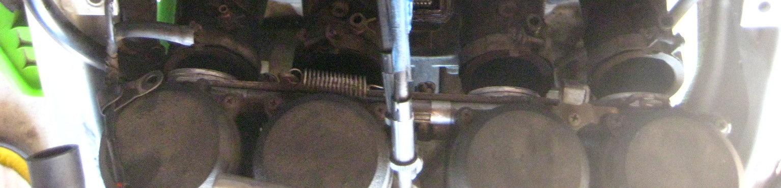
Now you are looking at your valve train and camshafts and sprockets and chain.

-Back to your pickup coil area. Use a 19mm socket and turn the motor CLOCKWISE (only!) until the 1/4 T marks line up with the upper 12:30 / 1pm O’clock position raised up built in ‘indicator’. I’m pointing at indicator below:


Look at cylinder #1 area (far left of bike sitting on it). The lobes should be facing away from eachother and up slightly close to 40 degrees / 45 degrees. If they face in, or cylinder #4 lobes are facing away from eachother, you have #4 cylinder at TDC. See here how #4 cylinder is at TDC.


Rotate the crank again at the pickup coil cover area a full 360 degrees which will put #1 at TDC.

The above green arrow is pointing to the #1 lobe facing out or away from eachother. (Arrow is not directional sign).
You can now measure your valve clearances. There are 16 to check. By setting #1 cylinder at TDC you can check all (4) valves of #1 cylinder, plus the exhaust valves on #2 cylinder, and the intake valves on #3.
Insert your feeler gauges between the camshaft lobe the the inverted shiny bucket below it. I am checking cylinder #3 intake valve while #1 is at TDC:

Feeler should have a slight drag on it but if you have to force one in, it’s the wrong size. Use the smaller number in that case. Write down each measured value for each specific valve. I made a rectangular chart with EX and IN tables and 8 boxes for each valve. Write down the numbers with something like that to keep track of each one. This is very important if you need to adjust your valve clearances. You must know all this information.
There are different spec values for the EX and IN valves. Clearance specs for our bike are this range:
Exhaust (EX): .22mm – .31mm
Intake (IN): .15mm – .24mm
Rotate the crank again at the pickup coil cover area a full 360 degrees which will put #4 at TDC. You can measure the clearances of all of #4 valves, the Intake valves on #2 and the exhaust valves of #3.
(You can also spin the crank again to the 2/3 T lines and check all 4 valves on one of the #2 or #3 cylinders if you like. It’s the same idea: as long as the cylinder’s Intake and Exhaust lobes face away from eachother and slightly up you have that cylinder at TDC and can measure the valve clearances for that cylinder).
If any of the valves are out of spec you will need to swap shims to alter the clearance to within spec.
If everything is within spec pat yourself on the back, you are done. Reassemble and go ride!
However, you probably will find valves out of spec if you waited awhile like me.
To remove the camshafts and to change shims and alter your clearances:
At this point, you actually want to have #1 cylinder at TDC. Recall if the indicator is at 1/4 T mark, either #1 or #4 could be at TDC right now.The manual glosses this over point, that either #1 or #4 could be at TDC just by lining up the 1/4 T mark.
Put #1 at TDC! If it isn’t (which way are lobes on #1 pointing – inward then #4 is at TDC), so turn the crank bolt at the pickup cover another full revolution back to 1/4 timing marks. This will now put cylinder #1 at TDC (#1 lobes are facing away from eachother right?).
The reason you want #1 at TDC instead of #4 is because the timing marks are much better and easier to understand and line up on the #1 TDC marks on the camshaft sprockets. Do not move the crank again once you’ve set it to #1 TDC and have started below procedures – Important!
Now look at your camshaft sprockets.
The rear one is the Intake marked IN, and the front one is the Exhaust camshaft marked EX.
You should see the IN — line at the rear of where the valve cover meets the head and the EX — line at the front of where the cover meets. They should be evenly horizontal. Below is the IN camshaft with factory line at the cover / case split:
Now count the links and / or rivets between those horizontal marks. My bike had the timing marks in between whole links. The book mentions links split the lines. Either way, use logic / math, the two lines should have 17 links between them and 34 rivets. If your marks are like the manual, you have 16 links and (2) half links between the marks which also equals 17 links (and 34 rivets).

NOW MARK your camshafts – both, and the sprocket with a line. THIS IS VERY IMPORTANT. I have written that in ALL CAPS, like I am almost shouting. It’s that important.
Skip this, forget this, and you have made more work for yourself and stress.  Make sure to mark them well. I used a metallic sharpie and that wasn’t the best as the marks nearly wore completely off from handling the chain. Paint pen / paint is best. Mark lines across both the chain and sprocket for timing alignment marks.
-Remove the CCT (Cam Chain Tensioner). It’s located under and in front of the carbs. I’m pointing to it.

-Remove the center bolt (12mm) first. This will release an under pressure spring and pin and copper washer with the bolt. Place aside.
-Remove the two outer bolts (10mm) now and remove the CCT housing from the engine. I had to whack mine with a rubber mallet, it was stuck in there pretty good. It popped out with some energy.
Now the camshafts have what’s called caps on top of them, big machined blocks of aluminum holding them down and inline (we could abbreviate them as Al Caps, haha).
 Look closely at the 16 bolts. They have little numbers beside them.
 Start to loosen the bolts a turn at a time in the order starting at #16 to unbolt (you tighten on reinstall starting with #1).
Do Not loosen the entire bolt. Just a little at a time to start until all the pressure has been released from the camshafts. If you don’t do it this way you won’t be able to get the caps off due to pressure misalignment.
You may want to remove the spark plug O rings here. At least be careful they don’t fall off and down into the motor:


Once the caps are off – again Do Not move the crank now again until the job is nearly finished!
When you remove the camshaft caps, be mindful there are 4 locating dowels in between the camshafts. They may have come out with the caps. Make sure where all 4 are, and that they are not missing or fallen down into the motor. They also have 4 very small O rings around them. I left mine in place as is (see pics). I ALSO left these lower spark plug O rings right where they were. This is where the manual insists to replace them. Anyway, I didn’t so there you go.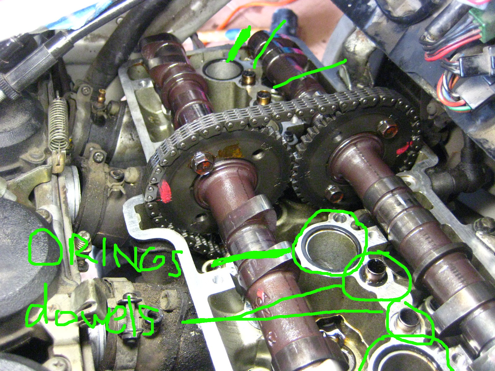
Next, You can in fact remove the camshafts without unbolting the sprockets like the manual says to do. You can move out the IN camshaft and sprocket together first and set aside.
 Have something right on hand to tie up the timing chain and keep tension on it so it does NOT come out of the teeth of the crank down below in the motor. Remove the EX camshaft and tie up the chain not letting the chain fall / drop / slacken much at all.

I used the throttle cables to tie the chain to.

With your camshafts out you have now exposed your buckets, the shiny metal round things upside down on top of your valve.


You need to remove the bucket and shim for any valve that was outside the factory spec value. You can leave in ones that are within spec. I had 14 or maybe 15 out of spec so I just pulled them all.
 The shim is stuck under the bucket in the above pic. Those shims are small! Like a small watch battery size.
I used a very strong magnet to remove them easily. With a strong magnet the shim should also come out at the same time under the bucket. Place the magnet center of the bucket for removal of bucket and shim together.
Take them out one at a time and put them in specific labeled spot for each valve. Each shim is different thickness if the valves have ever been serviced and it’s imperative to know which came from which for measuring. I used an egg carton and half dozen egg carton and marked one side IN and one side EX and put the buckets and shims in there to know which was which. 
So now you need to measure each shim that came out for any valve clearance you need to adjust and write down the precise thickness of them for each specific valve to tour table. Record final values in mm / metric as the charts are in metric as are the shim numbers for ordering.
So there are going to be a few figures for any valve clearance you want to adjust:
– Measured clearance
– Measured shim thickness
– Desired clearance
As the clearance are a range of values, you just need to get in that area. I opted for trying to make the valves all on the looser side of the spectrum as they will tighten with miles.
Then you can consult the Kawi manual lookup chart to find out what size shim you need to replace them with.

Write numbers down on paper, etc… I used a little whiteboard. The shims that are calculated to go back in are sitting on the board.
You can mix and match and replace with existing / used shims. You likely will find at this point you may have to go get certain specific shims that you need.
Basically the way this all works is, that generally the valves tighten up with mileage and the clearances lower / tighten. To get a larger clearance you need to get at thinner shim.
So if a shim that came out was measured at 3.00mm and your clearance was say around .20mm too tight for the spec you want, you would in this case replace it with a 2.80mm shim.
How about a specific example from my bike?:
On Cylinder #1 I measured my left exhaust valve at .038mm (way too tight!)
Spec for the exhaust is range of .22mm – .31mm
The shim that came out was a 2.95mm
Chart lookup value calls for a 2.70mm shim
New clearance once installed measured a .279! Perfect, the high side of the clearance range.
If you check some math there, the difference between the old and new shim 2.95mm and 2.70mm is .25mm
.25mm added to original measured clearance of .038 = .288 very close to the figure I got above. This is how it works. (in my case the .038mm feeler gauge could barely fit in between the lobe and bucket but it was the thinnest one my set came with).
You can calculate it yourself or use the chart. I used the chart to start, and then re-did all the math myself several times to make sure I was getting what I needed. I did not want to do this twice.
Once you have it all figured out (my first time – I took hours writing and calculating I think), get your new shims and install them in the proper valve spot. Then re-install your buckets. I kept my buckets stored and back in with the exact valve it came from.
Once they are all in it’s time for reassembly.
-Make sure your crank is still at 1/4 T mark.
Lubricate the bearing spots that hold the camshafts with motor oil. Or make sure they are still oily from before at least.
-Place your EX camshaft in first and line it perfectly back up with the link on the chain your mark meets up with on your sprocket. It will make this a fairly taut fit against the chain (and the crank below). That’s good.
-Install the IN camshaft next.
OK so here’s where you can toss some manual sh*t out the window. It states to have the camshafts in perfectly and flat down so that the IN — and EX — line marks are perfectly lined up with the case line and no slack on the chain. Yeah, good luck with all that. You’d need a circus strongman and or about 6 hands to shove the camshafts down on top of some resisting valve springs and hold it all perfect… plus it’s a waste of effort and time.
Think about it, the only thing that moves those sprockets is the chain which is only moved by the crank below. Even if there is some slack or not perfect lining up of the IN — mark and EX — mark on the case line, it will align itself.
JUST MAKE SURE your sprocket and chain link marks are perfectly lined up on both. You made those marks right? And that you never let pressure off your chain – and therefore let it slip off the crank sprocket deep down below.
Have the front EX camshaft tight-ish is nice (doesn’t have to be) and let the IN camshaft go where it’s going to go – it won’t be perfect. There will be chain slack between them. That’s ok, it’s all gonna fix itself.

If you removed any of the 4 locating dowel reinstall them and make sure the small O rings are around them. Also if you are replacing or removed the lower spark plug O rings, put them all back in now.
Now re-install the camshaft caps starting with #1 bolt. I tightened each one until there was resistance and then went slowly a little at a time in order #1 – #16. This will flatten down the camshafts. But don’t worry they are off yet. DO worry and make sure the chain doesn’t jump off either sprocket’s teeth.
By tightening down the caps, they will likely rotate and move around your camshafts a bit like how it happened to me below. This is ok, just Make Sure your marks are still lined up, and that there is the 17 links between the horizontal marks on the sprockets. 

-Once the caps are tightened to 12 NM (104 inch/lbs) of torque, YOU MUST reset your CCT. If you put it back in as it was you will likely break something and cause damage. Reset it.
You do that by pressing in the little button and then pushing back the little “plunger” (foot thingee) back into it’s holder. I’m pointing to the ‘button’ you depress to push the plunger back into the housing.
This pics shows the ‘plunger’ retracted after resetting it:

-Now re-install the CCT housing, the raised arrow on it aligns horizontally at the top (but not pointing ‘up’).
-Bolt in those two 10mm bolts on the housing.
-Reinstall the bolt, copper washer, pin, and spring into the CCT housing. It will be tad difficult as the spring will push back on you, but get the bolt in and tighten to 9.7 NM.
This will now engage the CCT to put pressure on the chain.
Make sure your painted on marks are all lined up and you have that 34 rivets / 17 links between the sprockets IN and EX lines.
-Now go turn the crank clockwise: Most likely you will see the slack between the sprockets go away instantly!
The chain will pull both camshafts where they need to be. Before turning crank:
After turning crank:
-Rotate the engine many revolutions to set the shims and make sure everything feels normal and sounds good. If you messed up the timing now is, well, the time to figure that out. Any major resistance stop! You may be mis timed and forcing valves into pistons.
-Now you will re-measure your valve clearances and make sure they are all within spec. If they are not – you know what you’re doing next. Figure out which ones are off, figure out the proper shim, and get it / swap it in from spares once you’ve taken the caps off again and the camshafts out. Hopefully you’ve gotten it all right and won’t have to do this (I did not have to).
If you have gotten them right – congratulations! You owe yourself a beer tonight.
So time to re-install it all.
What I did was turn the motor several times by hand to make sure it all felt right and then re-installed the pickup coil cover. I cut my own gasket for it as the old one was toast on removal.
-Then reinstall your valve cover and gasket. Make sure to use sealant on the (4) lower half moon cutout parts of the gasket – I used hi temp RTV silicone sealant. I got my cover wiggled back in less than one song on the radio – it was finesse-y but not too bad. I moved the wiring loom up a lot and slid it back in under the left side first.
-Reinstall the valve cover bolts and torque to 9.8 MM (87 inch/lbs).
-Re bolt in the black plastic heat shield
-Install the spark plugs.
-Install the coils and mounts back and the spark plug boots.
-Re connect the ignition coil wiring.
-Re install your carbs into the boots and tighten the band clamps.
-Reattach your choke cable to the carbs.
-Re-attach the negative terminal of the battery.
Now at this point I decided to test fire the bike. I had fuel still in the fuel lines and carbs so I fired it up with the tank off. It cranked a little as I had the choke in wrong position but fired right up and sounded great!
Then reassemble the rest of the bike.
-Reinstall ram air tubes.
-Reinstall airbox and then all vacuum lines and hoses.
-Reinstall the fuel tank and fairings.
Congratulations! Go ride!
This was my first I4 motorcycle valve adjustment. (I’ve done my 16 valve car before and an 6 valve inline twin Honda motorcycle – that was cake). It’s not a really difficult job, I just got agitated when I could not get any feeler gauge to go into the exhaust valves on cylinder #1 and #4 (because they had tightened to zero clearance and I did not know that yet) and a few things in the manual were not clear and an item wrong.
A weekend timeframe would be a good time estimate if this is your first time and you are somewhat handy in the garage. You likely have to factor in getting certain shims. You might be able to get this done in a day. But you will feel really good about getting it done and probably take half the time next time.
My motor sounds better, starts way better than it ever has since I’ve owned it, I have better low end power. I had 3 exhaust valves at zero, or less than .038mm anyway, clearance. I was risking burning a valve and probably had lower compression and power as a result. I was pretty thrilled to get this done.
Posted in DIY, repair and tagged adjust valves, clearances, DIY, DOHC, how to, i4, inline four, Kawasaki, Ninja, Valve adjustment, valve clearances, Zx6e, zzr600 by green
Debaffle stock exhaust Kawasaki Ninja ZX6e. Exhaust Mod. How to. DIY
This is a modification to the stock dual can muffler exhaust on the Ninja ZX6E 1993 – 2004 also known as the ZZR00 in 2004 and in Europe.
This was all inspired by “mechanicalmadness” member of the old zx6e.com forum. He did this exhaust mod and made a great write up although it’s gone from the internet now.
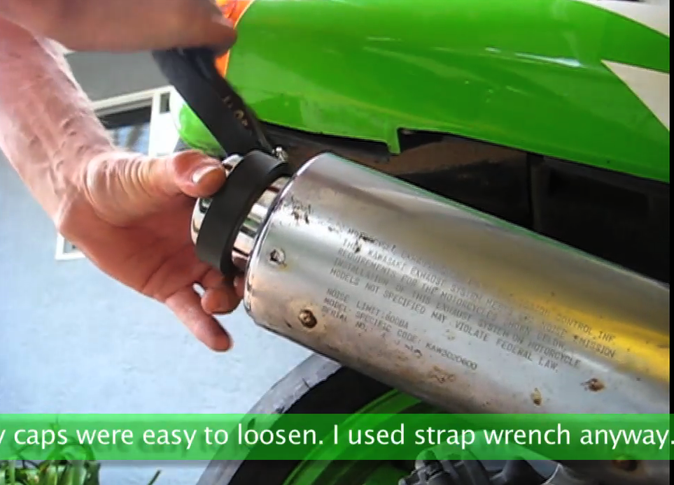
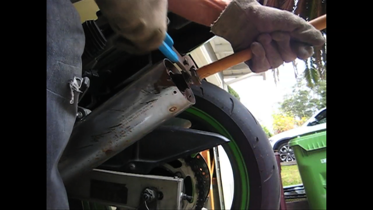
First thing, you have to drill out the exhaust cap rivets, there are three per side.
Next, you need to spin the exhaust caps out. I used a strap wrench. There is some sealant in there that does not let the cap release easily. Mine were easy to loosen though, perhaps due to their age.
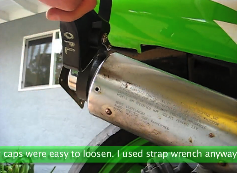
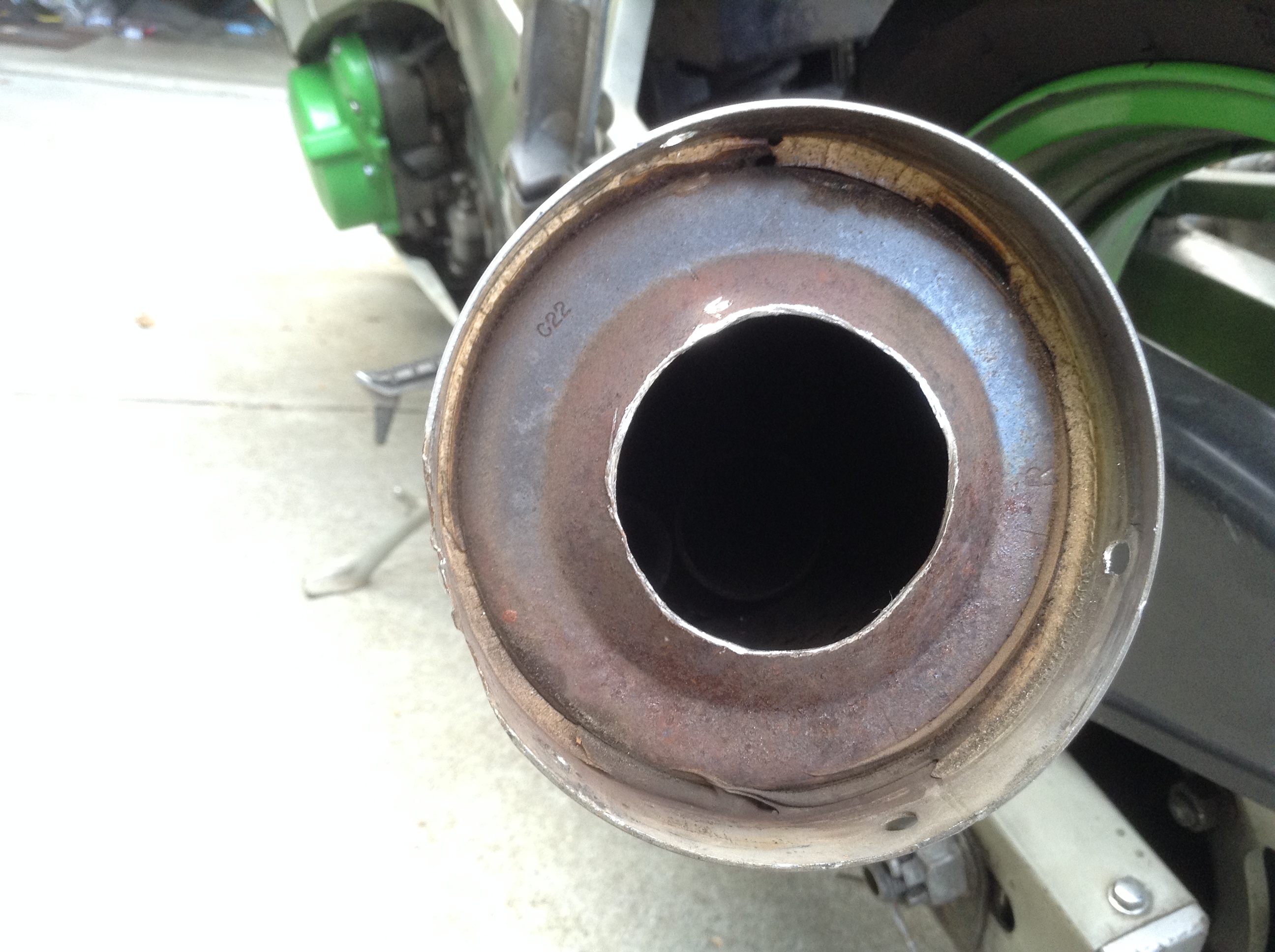
Removing the end caps reveals this:
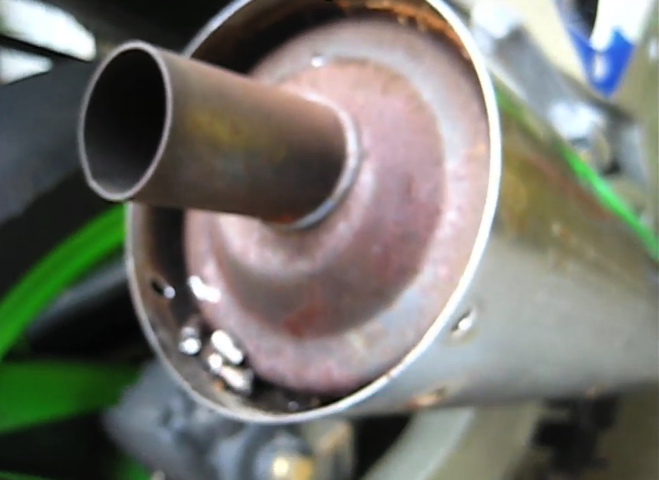
This is the final tail pipe that comes from 1 of 4 pipes inside as you are about to see.
Then, I used a 1 + 3/4″ (44mm) hole saw for metal to make it fairly easy.
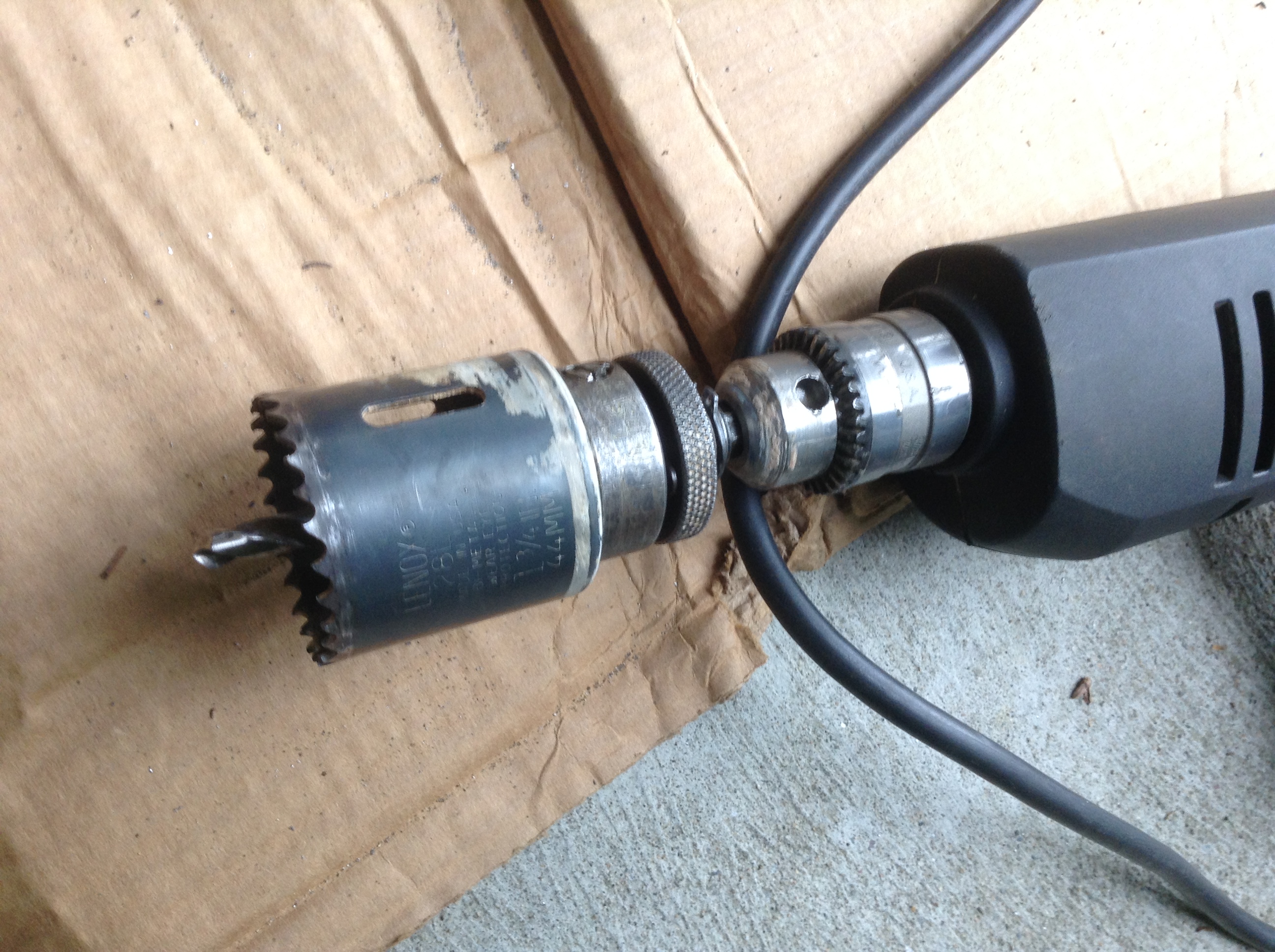
To get the holesaw to bite into the base of the end of the exhaust I cut the tail pipe off with a hacksaw first – maybe 1.5″ off or so.
Then the hole saw will easily reach the metal to cut.
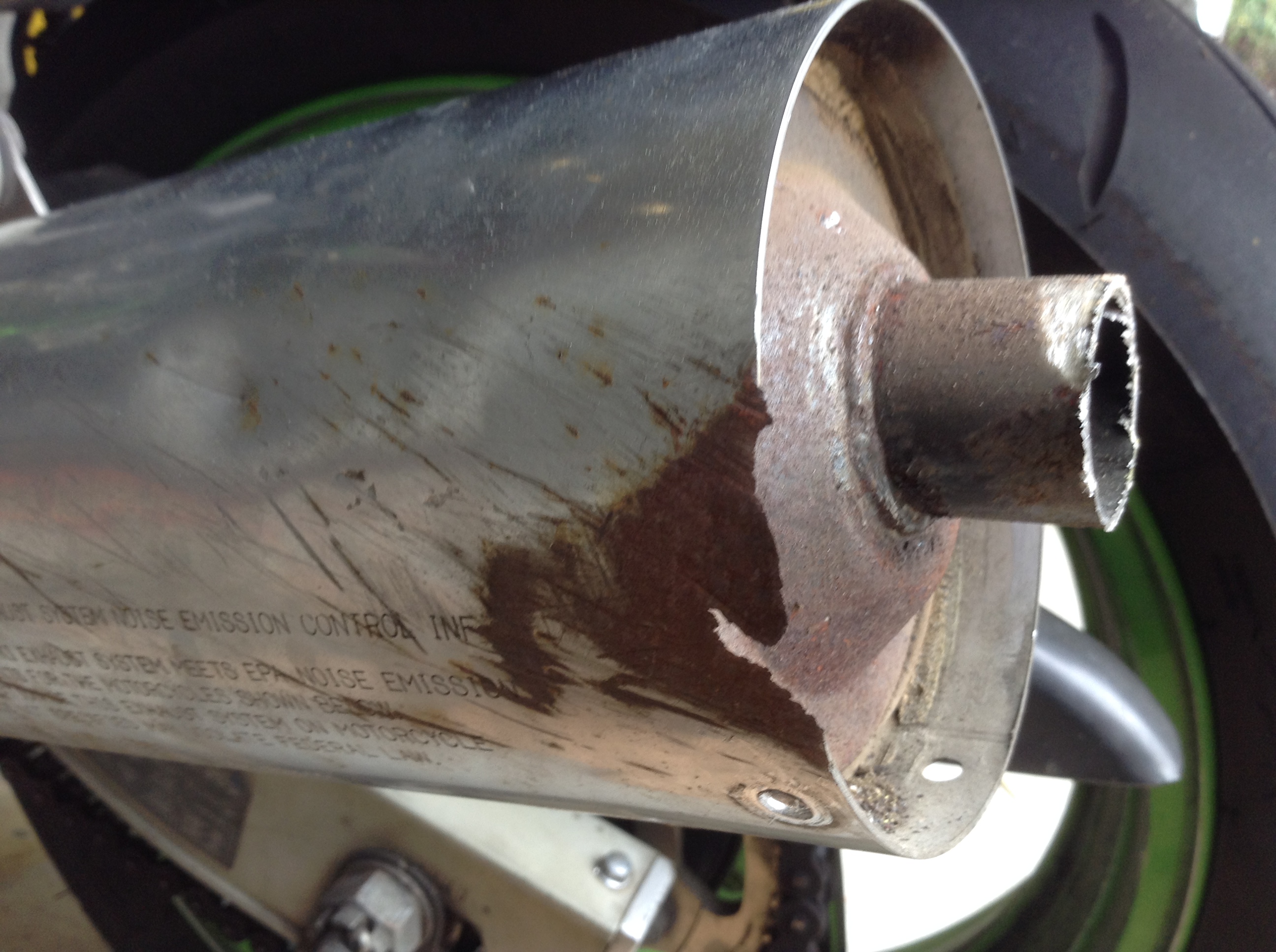
Once that’s done, you now need to break the inside weld spots on this tailpipe / baffle. I jammed a wooden dowel in there, and used lockjaw pliers to put a lot of force on it, mostly rotating. You might find this step easier with a larger hole saw hole, but I didn’t want to go too big here.
It took some time but eventually you fatigue the metal and snap it off and out of there.
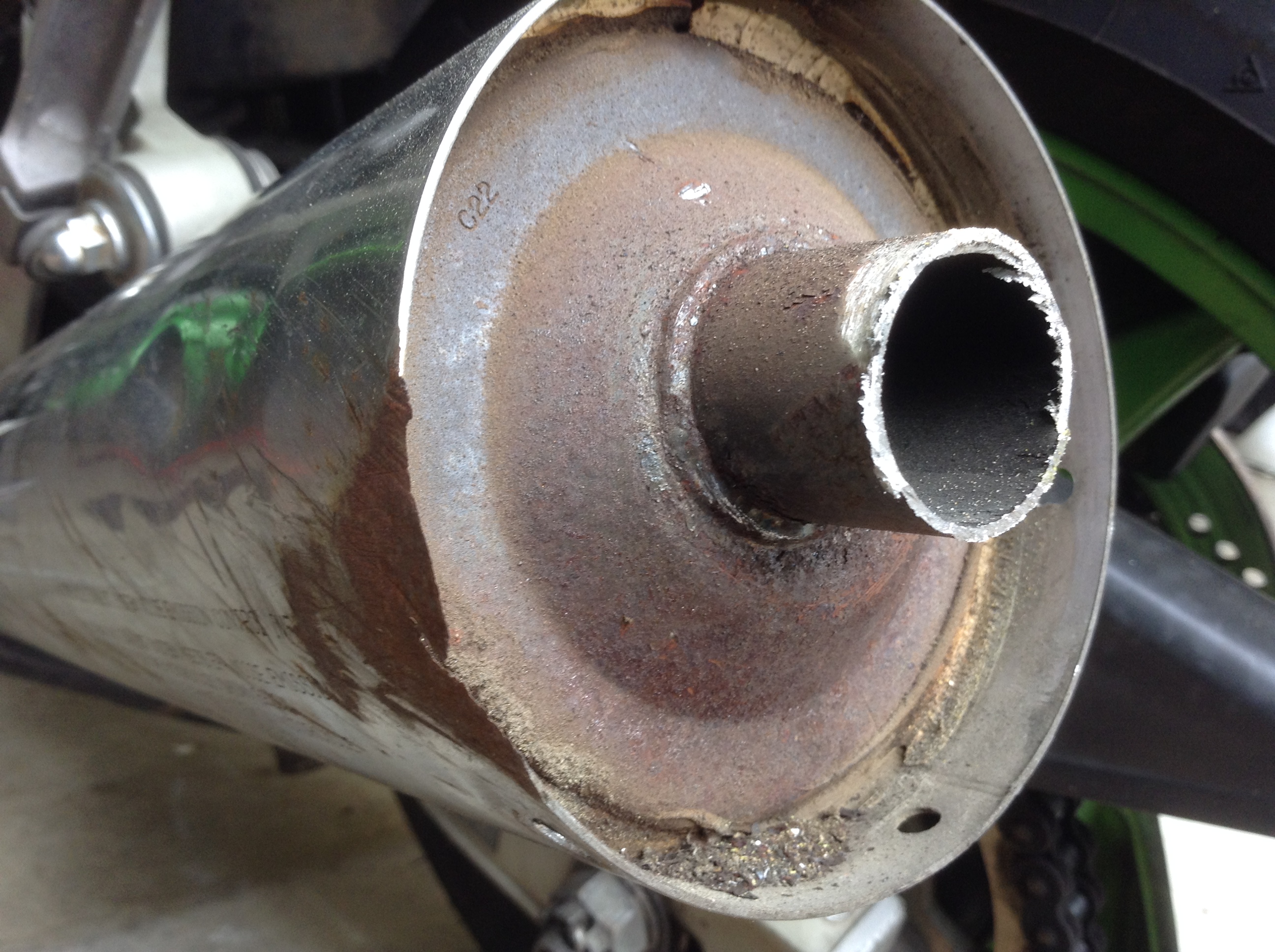
You can now see the insides of the muffler. You are looking at the plate of the middle chamber.
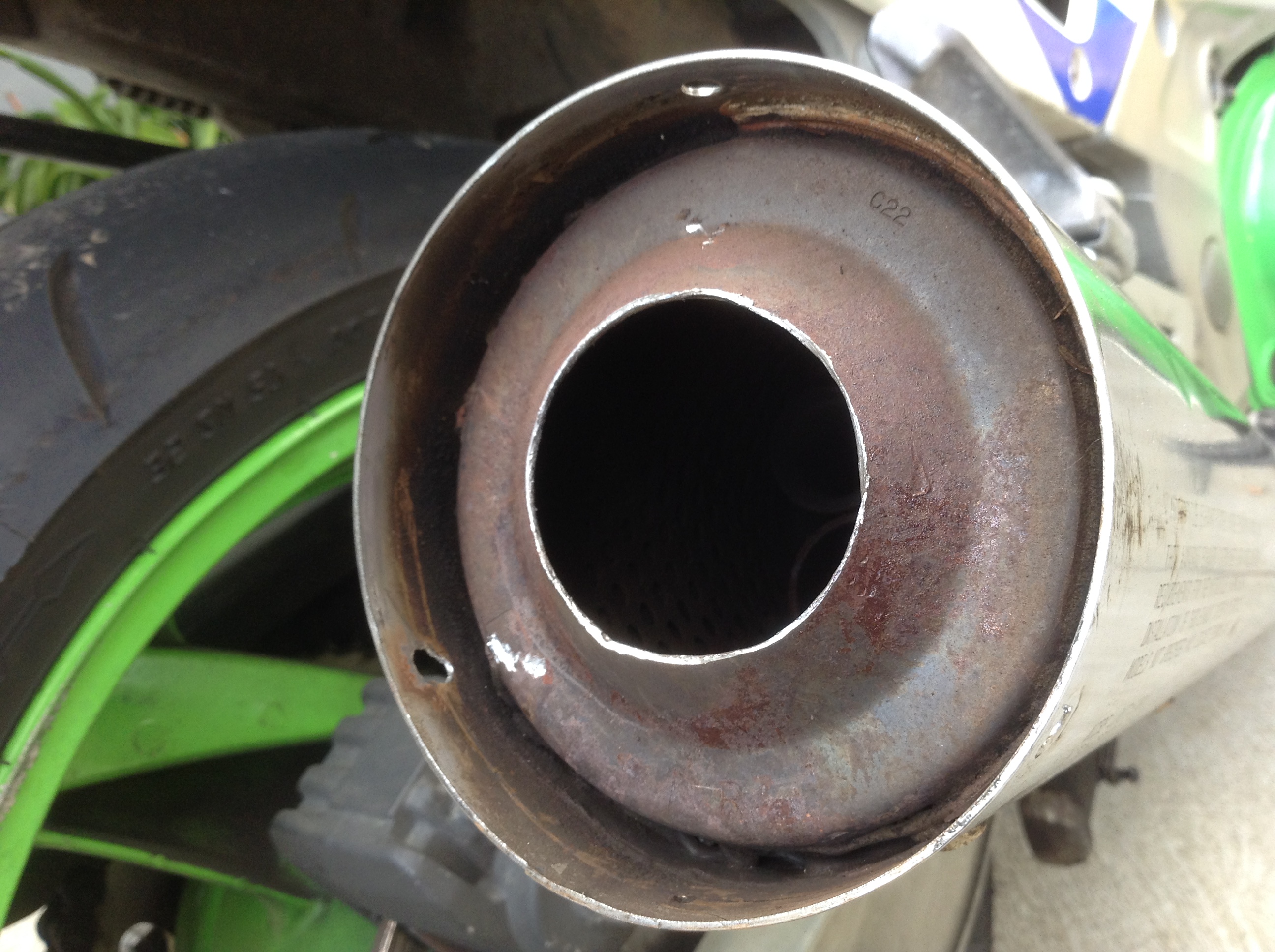
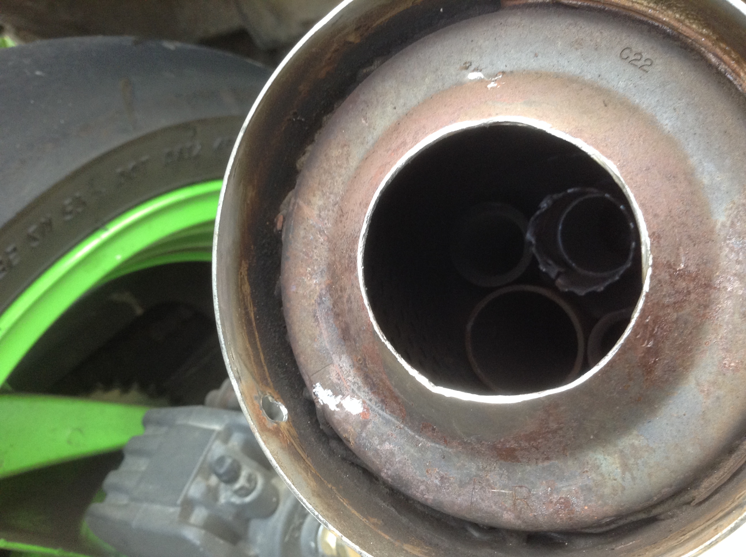

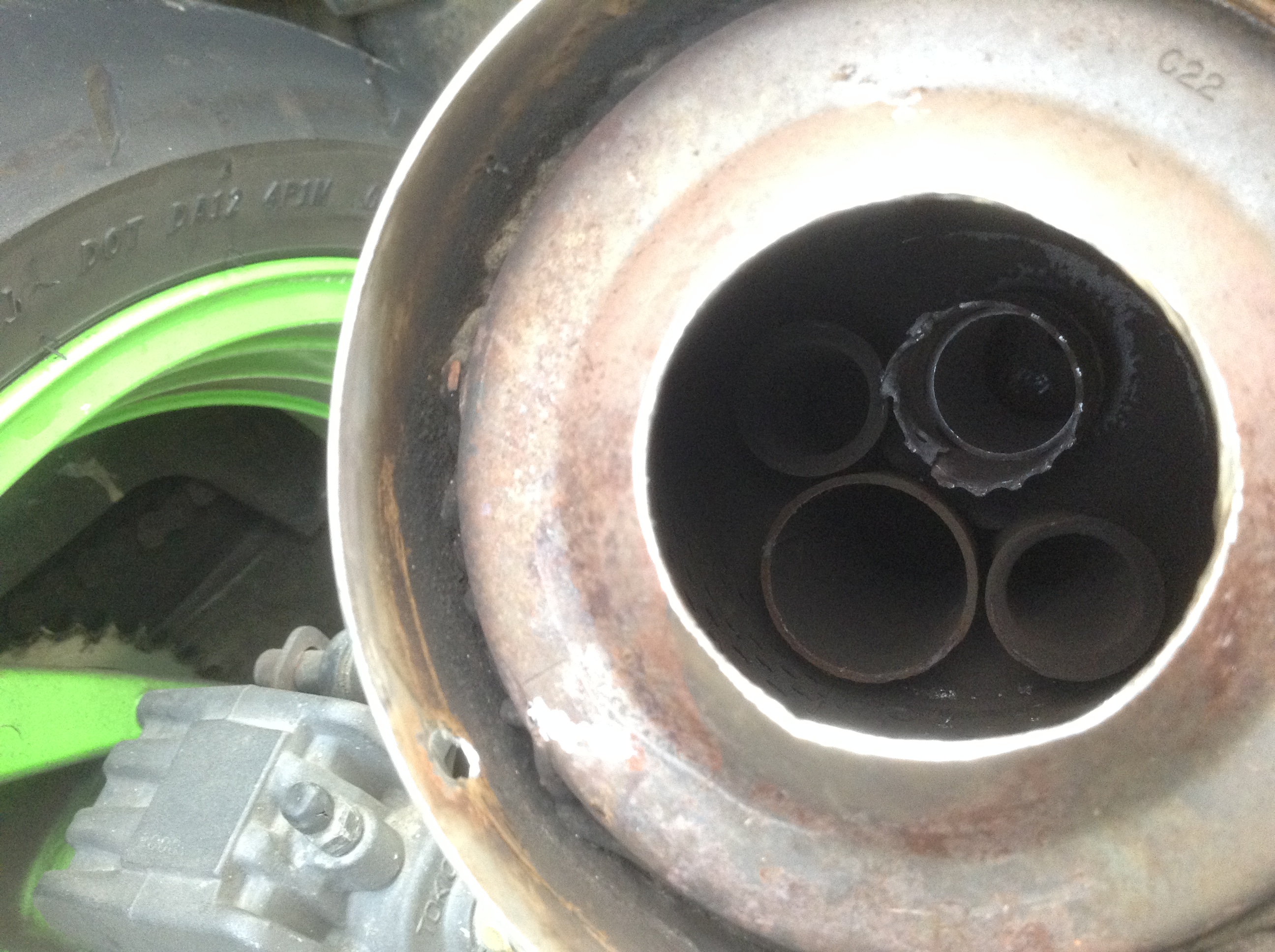
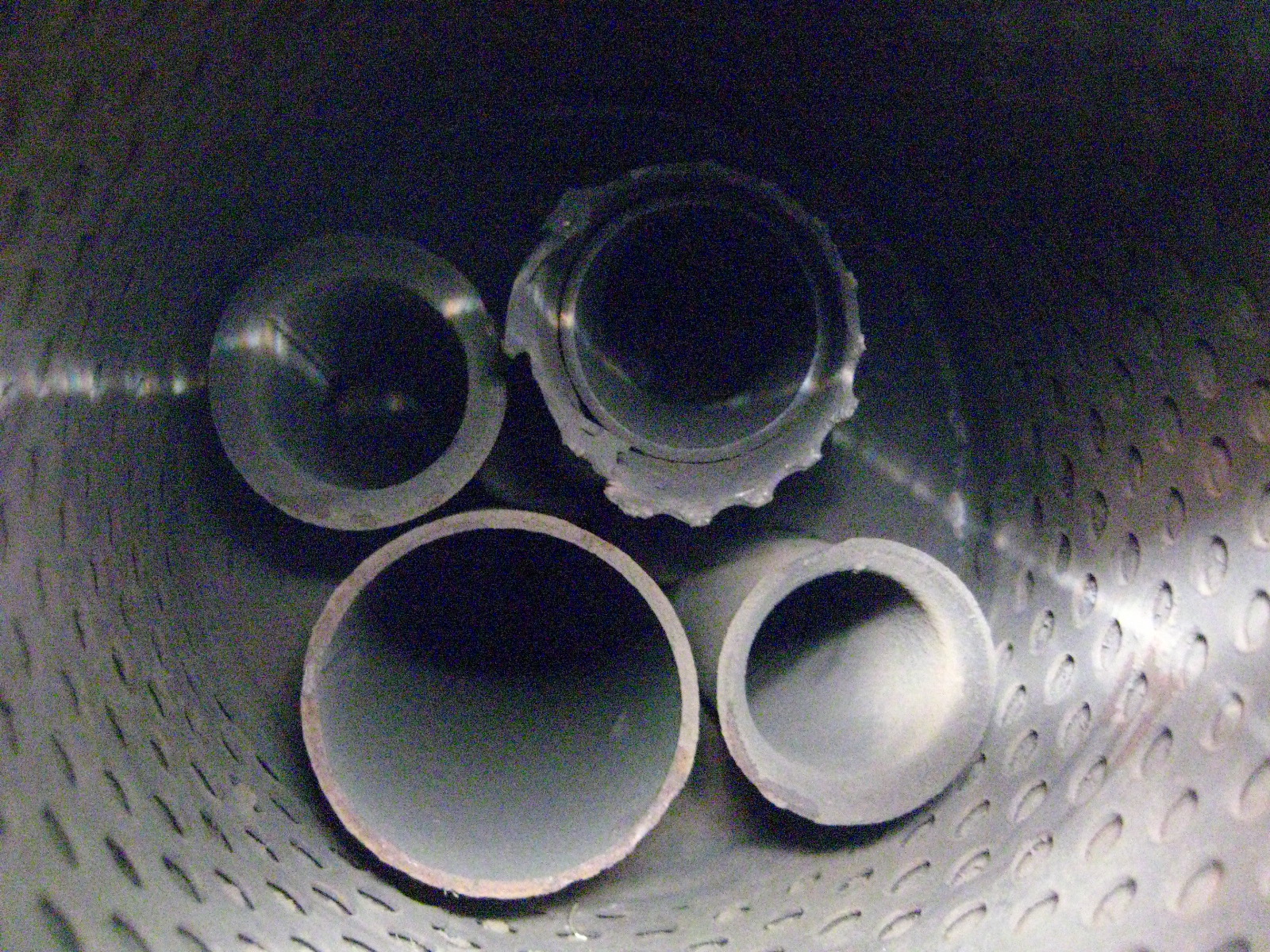
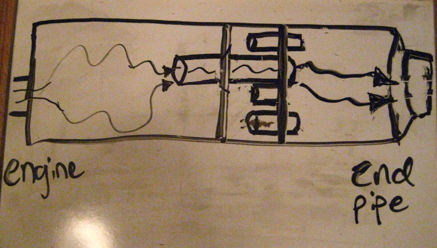
These exhausts have 3 separated chambers. What this mod does is effectively eliminate the middle chamber AND cuts out a large back and forth pattern the exhaust gases used to have to follow backwards into the middle chamber and then out that small final tail pipe / baffle. With it gone, the gases enter the first chamber and then exit out the larger diameter pipe, bypass the middle chamber altogether now, and then exit into the rear chamber and have free outflow out the back now.
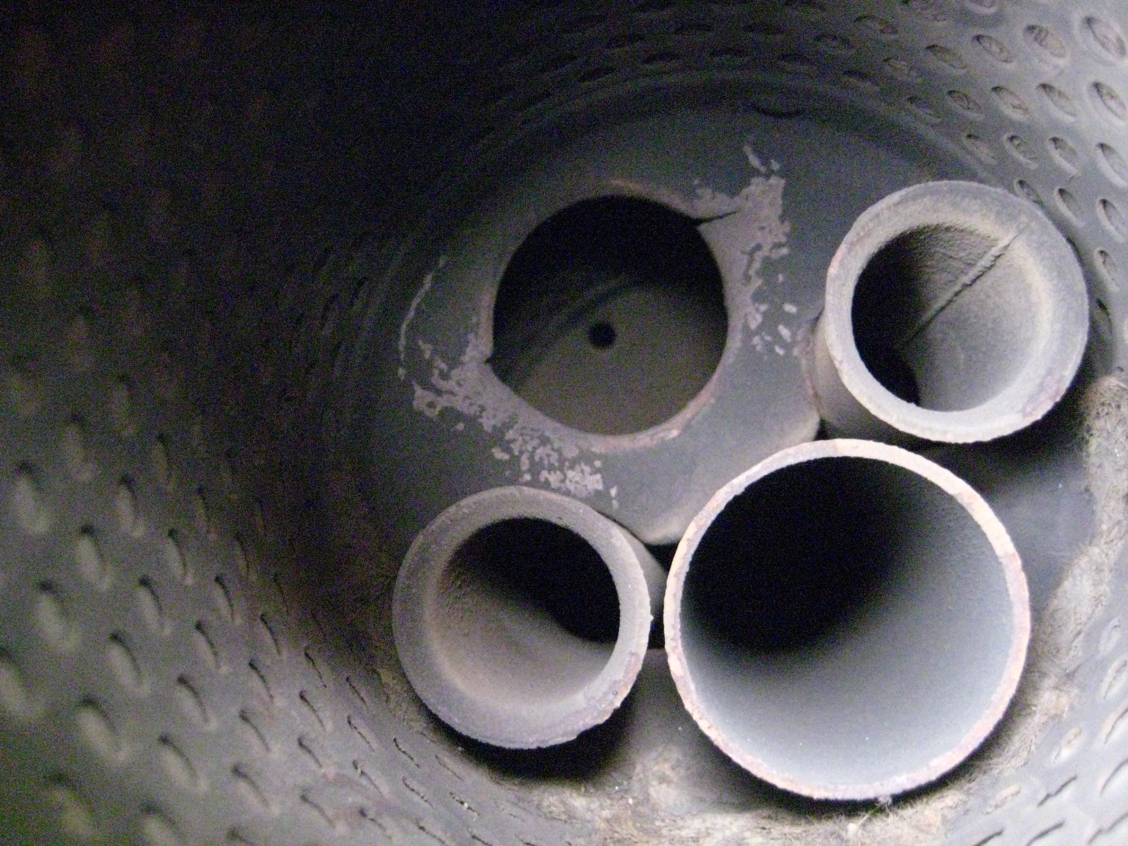
Before:
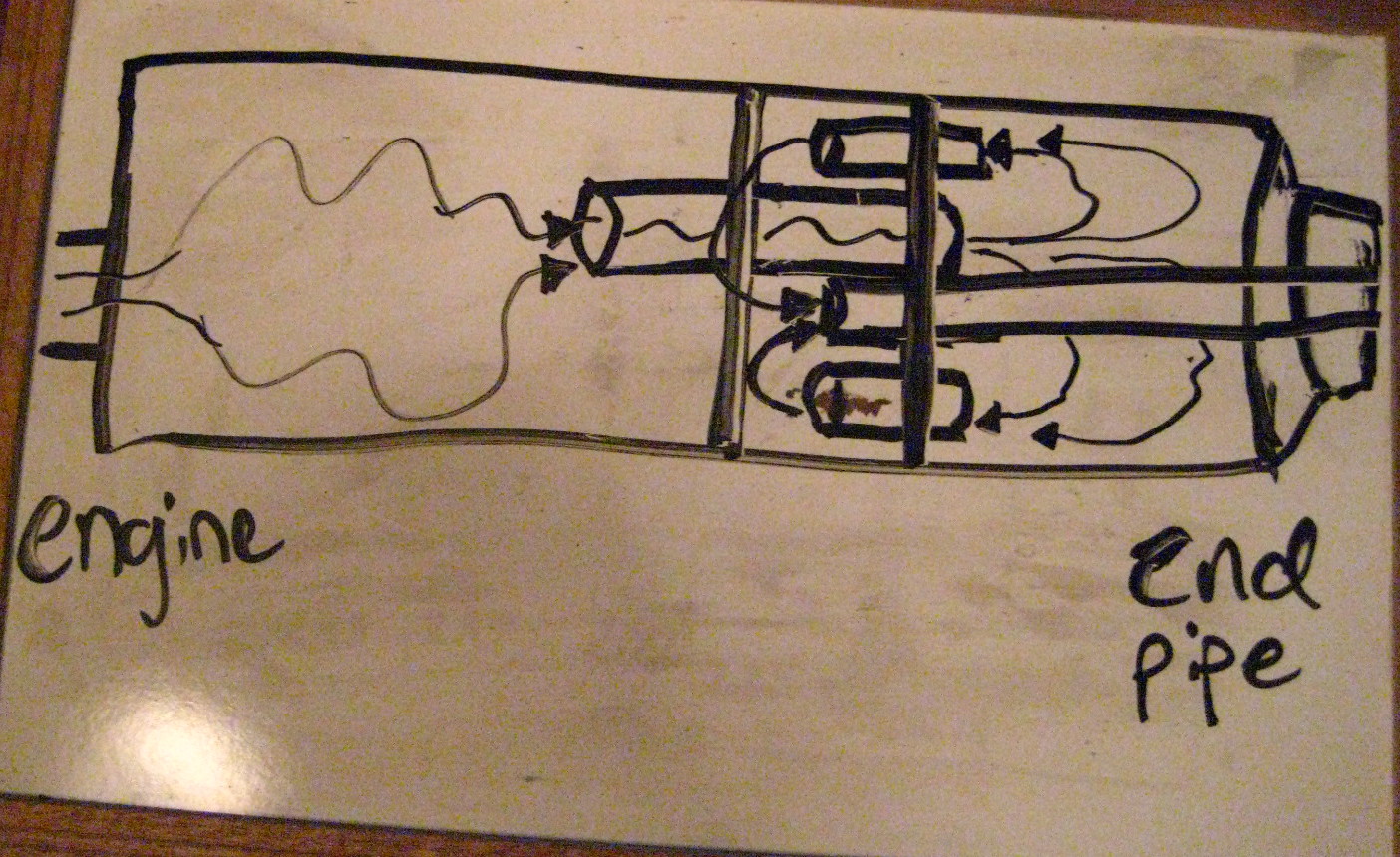
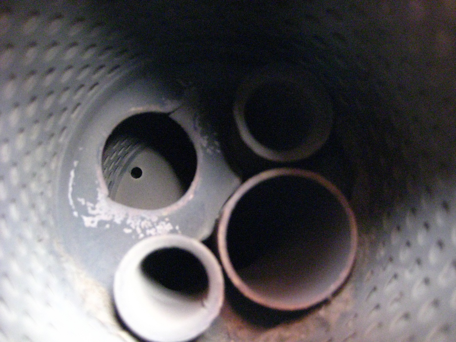
After:
Here is a photo of an ‘exploded’ stock muffler:
Yo
Result?:
It sounds SO much better than stock. Idle is amazing with a nice throaty burble. Cutting this all out rather than drill holes around the end tail pipe makes it deeper / bass-y sounding, and not raspy at all.
Depending on load and throttle position etc… it can get a little loud and drone starting as early as 3500 and through 5000 rpms. Again, depends on several factors. By 6000 + the exhaust sounds sweet and great!
My bike idle smoother at lower rpms with this as well. It burbles nicely, it really sounds fantastic.
This little mod has totally changed the feel of the bike. It was such a quiet bland exhaust before. Some people have done this and found it too loud for them.
I have worn earplugs riding for the past 2-3 years to protect against hearing loss (from wind noise), and I LOVE this exhaust with my ear plugs in. I am also noticed more by cars driving around as they have more of an audio warning I am nearby.
I will posting a proper comparison of the before and after video with same video gear with the same manual settings so you can hear the difference.
It’s a free exhaust tone modification and I did it in just a few hours on the weekend. Enjoy!
Posted in DIY, repair and tagged baffle, chop, debaffle, debaffle cans, debaffled, exhaust, exhaust mod, Kawasaki, muffler, Ninja, stock exhaust, Zx6e by green
Fuel hose Fuel Line size diameter 8mm I.D. 13mm O.D.
I’ve spent a lot of time searching for this info and finally figured it out. It’s hardly disclosed really anywhere.
ZX6E / ZZR600 use 8mm I.D. (Internal Diameter) fuel line / hose, with a 13mm O.D. (Outside D.)
In a pinch you could substitute 5/16″ hose as that seems to be much more common. You don’t need the common really thick auto parts version as that is used for higher pressure F.I. motors and we don’t need the thicker reinforced walls for carb low pressure fuel. Worm
One suggestion, Parts Unlimited makes a clear blue tinted fuel hose that is 5/16″ and they say long lasting and chemical / fuel resistant and fairly kink free (I think it’s polyurethane based). I got sold some 1/4″ Parts U. from the local Kawasaki dealer for my bike (wrong stuff – too small), and I have crammed it on, but it’s a p.i.t.a. to stretch onto nozzles, and then your old fuel line clamps won’t work as the O.D. is too small. It is pretty flexible stuff, stronger than stock it seems and it’s nice that you can visually see fuel in the system and moving for diagnosing / reassurance. It would be good for pump to carbs, fuel filter to pump, and probably pump to fuel tap / petcock runs. The short main and reserve to petcock / fuel tap runs have some pretty tight turns in them. So far I have left them and might order stock lines there.
BMW E28 era cars also use the same hose. You could get some 8mm from a BMW dealer.
Posted in DIY, repair and tagged aftermarket, diameter, Fuel hose, Fuel line, Kawasaki, kind, Ninja, replacement, size, sizing., type, Zx6e, zzr, zzr600 by green
Maintenance log Green Magic

43,174 8/15/12 Purchased!
43,295 9/16/12 Carbs cleaned (2 pilot air jets clogged), New fuel filter, clean & oiled Uni air filter, cleaned plugs, re-routed 2 hoses properly, blew oil out rear canister hose & rerouted, mixture screws reset from 3.4 turns to 2 turns, re-set idle adjuster.
9/20/12 throttle cable adjustment fixed, R/R wiring chopped and fixed.
10/08/12 New AGM battery
11/28/12 cleaned carbs again (were pretty clean).
11/30/12 fuel pump tested ok, checked for spark ok
2/8/13 43,305 Holy shit! Green Magic is back from the dead! NEW spark plug wires installed.
2/16/13 Oil change #1
2/26/13 installed painted green windscreen, fuel line clamps installed
4/8/13 blue carbon fiber seat cover installed
4/24/13 white mirrors installed
43,697 5/2/13 replacement regulator / rectifier installed
43,950 6/16/13 coolant replaced and flushed
9/30/13 chain tension checked and ok less than 1.3” slack
9/29/13 Double Bubble windscreen installed
45,381 2/1/14 Green LED gauges installed! installed ram air guards
46,439 5/4/14 Tire swap #1 to Dunlop Q3
46,931 5/17/14 Oil change #2, epoxy try on stator cover (x)
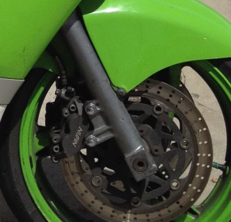
47,292 5/24/14 ZX10R rear caliper installed w steel line
47,696 balanced rear wheel
49,469 10/13/14 New Clutch, stator cover leak fixed + painted. replaced clutch rod
Oil change #3 – Rotella T6 and Purolator from now on.
51,600 2/23/15 cleaned carbs, cleaned out starter jets, last 2 new float bowl gaskets installed
53,884 3/16/15 Oil change #4
54,860 4/26/15 Tire swap #2
54,860 Nissin brake calipers mod installed ’05 F4i brakes, front and rear brake fluid swapped.
2nd re-crimp of R/R wiring. Shock pulled and Fox TC lined up.
55,318 6/10/15 water pump repair started
55,435 6/13/15 “Hot idle” problem fixed – loose coil spark plug wire deterioration issue.
56,284 6/20/15 re-balanced front wheel, brake cleaned front brakes
57,320 8/9/15 sanded off gas tank p.o. damaged rust spot and painted white, JB Welded cracked clutch cover
57,998 8/22/15 installed replacement Kawi front brake lever
58,241 8/27/15 installed replacement thermostatic fan switch
8/30/15 installed replacement clutch cover, green painted clutch lever,
bar end for drop damage, clutch knob
57,998 8/33/15 Adjusted chain slack, reconnected speedo cable that had fallen out.
58,321 9/6/15 Oil change #5
58,250 9/3/15 fixed replaced clutch cover leak, verified fan comes on. re-bent clutch lever back.
10/9/15 clutch lever stripped to bare metal aluminum at D.C.
59,646 11/02/15 rebuilt fuel petcock (didn’t need it).
59,982 11/08/15 Exhaust mod. Chopped out baffles. Debaffle. Installed new 5/16″ Parts Unlimited fuel lines
60,401 11/18/15 Valve adjustment job. Ignition coils replaced (both). New spark plugs, adjusted throttle cables.
62,470 2/12/16 Gold X Ring chain and sprockets back to factory 16/48 teeth. 3rd set of tires: Michelin Power Pilot 3
63,134 2/23/16 Oil Change #6 (Pleasanton street after shoot #97)
63,325 5/9/16 stator to regulator / rectifier re-wire upgrade to 10 gauge THHN wire (2 white and 1 black runs)
63,465 6/28/16 carbs dumping fuel. 3x, 4th after running bike with petcock ‘off’ and sitting 2 hours and no leaks
63,567 7/1/16 headlights lo and hi beams repaired. Hand grip wired back to stock. New lead back of R/R white stator to junction box old yellow connection (new blue wire).
Posted in DIY, repair by green
Water pump rebuilt.
I can indeed confirm this Honda oil seal part fits the ZX6E / ZZR600 model:
Honda part #: 91201-MF2-003
description: OIL SEAL (12X28X7)
price: US Dollars $4.99
I had to special order the part and installed it today. Very nice fit. This is the oil seal that goes around the impeller shaft at the very end (not the wider O Ring that goes around the water pump impeller housing.
Posted in DIY, repair by green
Nissin CBR Honda brake upgrade fitted! DIY How to
Nissin CBR Honda brake caliper upgrade How to DIY
I bought a complete set of Honda CBR F4i front brakes for just $20!
That included everything, the calipers, Master cylinder, all brake lines, pads, and even the lever at the m/c.
I wound up combining them with the stock ZX6E brake lines, master cylinder and brake lever. Was just a little easier that way to install.
Took some grinding on the fork tubes with a file in two places on each one, plus filing down the Nissin calipers themselves in one spot and removing several nickel thicknesses there, and I also had to deal with the different bolt in sizes.
I opted to tap out the Nissin caliper holes and use the stock ZX6E brake bolts to their tubes. This way is safer I believe and also I can swap back to a stock setup quickly in a pinch. No shouldered bolts for me.
I borrowed a friend’s M10 1.25 pitch tap and that did the trick.
Posted in DIY, repair and tagged brakes, nissin, upgrade. braking, Zx6e, zzr600 by green
Just bought CBR Nissin front brake setup! $20!!
After work today rode north to the city and the sunset district. I rode up and down the great highway at ocean beach a few times, bought the parts and stashed them in my tank bag, and then rode up to the cliff house and the park overlook, and then back down to the small beach south of Noriega and rode through the fine sand all over the road there to get to beach parking with my completely shot tires. That was interesting. It was really nice to cruise around the beach and oceanside after work.
Found a really superb deal on a 2004 CBR F4i Nissin complete front brake setup.
I got the master cylinder, lines, calipers with pads with lots of life left, and the brake lever too! Guy wanted $30 for the set and then charged me $20 when I got there as I just had twenties on me, and he said he had been trying to get rid of them for a long time. (He bought that off another guy just for the steel lines and he threw all this in the deal).
Stoked! I keep reading especially on zzr-international.co.uk site and a little on the zx6e.net site about how amazing of an upgrade this is to the stock Kwawk.
I have to adapt from the Nissan’s 8mm mount holes to the Kwawk’s 10mm bolts. I’m planning to tap out the calipers to an M10 pitch 1.25 using a 11/32 drill bit first and the M10 tap after. I think this is the better solution.
My best friend is flying in from the east monday and bringing with him his M10 tap. I will probably borrow a drill press locally from the local tool lending library here.
Have a busy number of days ahead with Green Magic:
– New Tires priority #1!
– New brakes while wheels off and front brakes unbolted for tire swap.
– Going to remove stock rear shock and finally at least size up the Fox Twin Clicker. I need to machine a number of parts, but this will help me gauge what I need compared to the stock dimensions on the upper bushings etc…
– Water Pump looks like it’s failing or failed. This past week I noticed spewing coolant under the pump on Tuesday, and Wednesday, and Thursday i noticed oil coming out the weep hole I think on the pump.
– some fairing white sticker work to cover previous owner low side damage.
– re-painting green the bar ends after sanding off the new surface rust
these jobs will also be my first brake fluid change on the front end since buying the bike, and also be my second coolant replacement, and that’s due anyway.
Posted in DIY, Uncategorized by green
How to replace Clutch on your ZX6E Ninja. Easy, step by step how to DIY
In my opinion, this is a very easy job and not much harder than changing oil or spark plugs.
Easier Tips: An easier way to is drain your oil. You can gangster lean the bike a lot towards the kickstand side of bike. I’ve read pushing bike onto 2x4s and using sidestand should make it not leak much when you pull the clutch cover, but I was near my oil change interval anyway, and figured I’d rather have more secure stable bike to work on, on the centerstand.
I also pulled my clutch lever in, then held the lower clutch lever down below on right side in place with a short 2×4, and disconnected the cable at the handlebar. I then rotated the lower clutch release rod, it’s attached to the hinged lever down on the lower right bottom of the clutch housing where the clutch cable hooks into. The rod is inserted up inside the clutch housing. Rotate the rod gently to free it, and then slide the rod out the bottom of the housing.

1) Drain oil (or not – see above)
2) Unbolt the clutch cover.
It’s the lower right large cover on side of bike, where your fill up your oil. There are about ten 8mm sized bolts you need to remove here. With the old gasket installed, it may be a little stuck on there, I gently, and I mean gently, gave it some taps with a 2×4 scrap to help free it.
3) Remove the cover.
Voila! you’re looking at your clutch assembly. Yes, it’s this easy.

4) Remove the five allen bolts that hold the clutch springs in.
They are long bolts and unscrew slowly, so don’t worry the springs aren’t going to shoot out at you or anything. You now will see your clutch metal plates and friction plates all stacked in on the clutch basket.

5) Remove metal plates and friction plates.
Just pull them out with your hands. Keep track of the order of them as you remove them and stack them. Basically, they alternate a friction plate, a metal plate. 7 friction plates in total. These are what you will want to replace with your new clutch kit (along with springs most likely). My inner most one was worn to 2mm, way too worn. They need to be at least 3mm, and a mm here or there spread out over so many plates adds up! (That’s what caused my clutch release rod to slip out, not enough thickness overall to the clutch plates due to wear. And picky shifting needed with the clutch this worn. I had lengthened my clutch cable {loosened} it to the maximum length and had nothing left.)
Look at your metal plates too. If you cannot see the little ‘dimples’ in the plates, they are almost certainly too worn down. 
 The divots just give the oil a place to hang out, and help keep the plates lubricated and freer. Check for excessive wear, and warpage. Easy way is place the metal plates flat on a piece of glass and try to slide some thin gauge feelers under them at numerous spots. Anything over .05mmm means they are warped. You should consider replacing warped or very worn metal plates. Otherwise, most people sandpaper the surfaces a little to scuff them up and reuse them.
Here, I scuffed the metal plates up with Emery cloth ‘fine’ sand paper:

6) Soak your new clutch friction plates in your motor oil for at least 30 minutes if not longer before installing, this helps avoid excessive wear on the dry plates on the first startup.
7) Remove all the old gasket material on the cover and the motor side.(I carefully used a razor blade).
8) Reinstall your new friction plates and metal plates alternating. The final outside plate does NOT go in the same deep slot grove in the clutch basket like the others do, rather it gets rotated slightly and fits in it’s own separate tab.  You can see that outer shallow tab opening in the above clutch housing photo above. See where the red line is pointing to at the top (not where the white text bubble has a small pointer). This is important to get this correct to avoid clutch slippage later.
Replace your new springs unless you decide to use your old ones.
9) Fit your new gasket (or something like Permatex gasket maker), and mount the cover and rebolt it in. I make my own from FelPro gasket paper.
Here are my new friction plates installed. Notice the outside friction plate is aligned in separate cutout tab in the clutch basket.


New springs and cover installed:

Reinstall your clutch cover and tighten according to the torque specs, which are 8.8 Nm or 78 in-lbs. They are not super tight. Push back in your clutch rod if you removed it, make sure to gently insert it and rotate it so it catches on the clutch release pin under the cover. Also, hook back up your clutch cable if you released it.
If you drained oil, add new oil. Make sure to not sure regular 10W40 auto oil, it has friction modifiers which can make the clutch slip.
Now make sure to adjust your clutch cable as it will be different from a worn out clutch. Adjust at both the handlebar and by the clutch housing the cable adjusters.
You can find special motorcycle Valvoline 1040 wet clutch safe oil, for example. I’ve used that the past two oil changes but I decided to switch to pure synthetic oil this time around doing my clutch to Shell Rotella T6 5w40 diesel oil. I’ll post on this blog how I like it, I’m hoping to have cleaner, smoother shifts!
UPDATE: I love the new clutch and I’ve ridden several thousand miles on it with the new Rotella T6 synthetic oil. I have much much smoother shifts with the new clutch.
Posted in DIY, repair and tagged clutch, clutch plates, DIY, friction plates, how to, Kawasaki, Replace, replacement, yourself, Zx6e, zzr600 by green
ZX10R ’06 rear caliper brake swap!

Mileage: 47,292
Yesterday I just changed out my ’95 stock caliper to a 2006 ZX10R. It’s a direct swap. No mods needed. (Other years of similar era would work too, just check).
Although same lackluster performing caliper they are easier to find, cheap, newer, as quite a few 10 owners upgrade and have them laying around. Had to change pads anyway, and this was almost priced as same price as pads alone.
I bought the entire unit for $40 with about 6K and almost no use (off ex-race champ who never brakes with rear except trail braking). It had been upgraded to steel Galfer line, EBC sintered metallic pads. Came with brake piston cylinder, lines, reservoir, brake lever, clip on, and fluid all still attached with piston freely moving.
Some interesting things happened. Was going to try to swap everything, but found even though the brake cylinder looked identical with same number on front, it has a different part number stamped on the back. And it’s length to the pivot on the foot brake lever is shorter by about 1/2″ or more. I was going to try to use it anyway, figuring it was newer, but I also realized I’d have to mess with the brake light sensor unit and change its length on the collar if I could etc etc…. And at 9pm at night wasnt wanting to make it a longer project. Basically if you just bolted it in as is, the foot brake lever would drop lower, and have less travel to brake, and the brake light would probably be on the whole time unless you adjuster that plastic sensors length (it clearly is adjustable but how far and which direction I did not experiment with after deciding to keep my stock cylinder, upper hose,mand stock upper reservoir.
In fact, the caliper is listed as a different part number but fits no problem. The pads are identical to both ZX6E and ZX10R 2006 era and other years.
The Galfer steel brake line was quite long, and I had to flip over both banjo bolt ends
As they seemed to be angled wrong.
The upper reservoir looked the same, but looking closer the feeder at bottom was in reverse position, and then I noticed it had upper and lower markings on both sides! So although its different Kawi probably had it doing double duty in multiple bikes. The brake hoses are wider gauge on the E stock unit all around compared to the ZX10R.
So in summary, easy caliper and pad swap out, no problem at all. Everything interchanges and mixes and matches perfectly. Brake works great now too! Lots of bite in back now.
Lines and banjo bolts all match and bolt threads etc…
The ZX10 brake cylinder could I feel be used – it has identical bolt in position and pattern to footpeg brackets. But you’d probably have to lengthen the pivot bolt by loosening the nuts and extending the pivot down (I did that in fact but stopped the install due to other reasons.)
The upper reservoir could be used with zx10R hoses to cylinder if all off same bike, but you would probably either have to mount it backwards up top, and have the angle of the outlet at bottom pointing slightly the wrong way or better yet just make a metal extension piece to keep the reservoir facing the way the E wants it, it would be like a 3 or 4 inch piece with a mount spot.
ZX10R complete setup as purchased in pic below.

Original stock unit before replacement. Pads totally shot.

Posted in DIY and tagged caliper, rear brake, upgrade, ZX10R, Zx6e, zzr600 by green
“The Duct Tape Method” DIY change tires motorcycle yourself without tools! How to
I double taped about 2-3 inches or so on about 16″ strips. So lay out long strip and cut a short piece and tape over it so the two sticky parts lay face together stuck together. Why? That’s the part you line up with the tire inner bead part. This way you can pull it out easily and fast after tire put on.
CLICK pic below to see my video here:
I taped the sticky long half under tire pressed two walls together – which is SUPER easy with the Q3. Mine was soft as butter after spending about 6 hours inside a normal temp apt. Did it with a finger and a thumb it’s so compliant.
Space those tape points roughly out the same. Then I used just a little dish soap and water mix around the tire and wheel half where I’d have to push.

I got it about 65% on and it started getting very tight. This is where I said in my head “there is no f-ing way this is gonna happen” But I made sure the already mounted portion was snug squarely in the center of the wheel and therefore its smallest radius. In fact I kind of man handled it pretty good and stuffed it and made sure it was snug in there. That made a big difference – even though it looked the same before, it wasnt. Smoosh that tire up in there inside that middle part of the rim!
Then I pushed on both sides of last 35% of tire and in about 30 seconds it just plop! Slid right over the wheel rim!
I was shocked that worked. Aired up a gas station to about 70 psi and got 95% of bead perfect in. 2nd to last bead I had to bounce a lot and more air to 70 and it POPPED in loud. Didn’t want to go higher air pressure and bounced it a lot, finally tossed in my car trunk with one last part not fully seated – although holding air just fine for now. About 25 minutes later it had seated itself perfectly. Aired down to 40 lbs and voila! New tire!
(The old tire I chopped up a lot before breaking the bead – not good. Not recommended, break bead fully first! Although by slicing through one entire sidewall and having 2 separate parts I was able to dismount the tire with my bare hands and not much force. This is coming from the guy who can hardly center stand this bike so I’m not the most ripped person on earth I’ll tell you that! Think computer user body build). No irons no spoons NO rim damage!
Finally broke both beads on the front tire. Was at it 1-2 hrs. So before I forget, I’ll post tips.
I borrowed two craftsman bar clamps with the squeezy grips. Another C clamp style one was worthless. These two is what I needed. The 8″ wooden angle changing one that Pengaru has in the tire change DIY sticky would be a lot better.
Set both clamps about 4-6″ apart on wheel. I tried and tried and tried. Was about to give up. And I recalled how I chopped through rear tire. 
So I sawed horizontal cut through front tire, and was able to push in tire. And I coated inside it up a lot with water and soap and that’s what finally enabled me to break it free, lubing inside bead and tire area. If you have trouble with clamps do that and it will help a lot.
I didn’t have an easy ability to make the wooden 2×4′ eight foot lever using a car thing, next time I’d prefer to try that or get the wooden clamp. This method was a lot of grief.
(I couldn’t push this one off like the rear, wasn’t even close to going. Tried clamping sidewalls together and that’s closer but not close enough.)
Wow, getting old tire off and new on was easy! Not really harder than rear wheel.
I used DUCT TAPE again to get old tire off and new one on. No extra cutting.
Now just need to air up

Edit: I put the f ing tire on the wrong direction this time. I was so pissed.
I just had to completely redo it BUT it did go smooth once re duct taped it again AND I shot a video of it this time. Should not have forgotten to check direction. But at least its on and right direction.
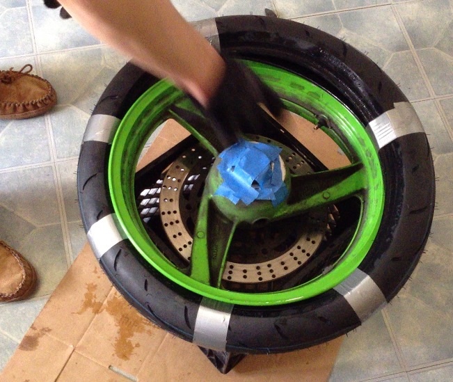
I’ve just slipped both sides together off the rim with duct tape. A milk crate underneath works great for protection.
(I did remove the right rotor but don’t real need to if you’re careful. Next change I won’t bother).
This is how I duct taped the tire beads together to slide it off the rim (didn’t take a ‘before’ pic).
I did actually use a small zip tie to fish the first piece of duct tape between rim and tire. After first tape piece is in its much easier with more space to work. Notice hacksaw cut for applying inner lubricant for breaking the bead step earlier.

The brand new tire all taped up and ready to try installing. This was my first attempt on a front wheel ever and it went on a lot easier than I thought. I recommend duct tape because its a wider band and will potentially cut less into new tire than a zip tie, not scratch rims like a lever could and most people actually have duct tape on hand!

I made my own little wheel balance station like this below. I leveled (with a level) side to side and front to back two milk crates on a small table and then used the actual axle to mount the wheel and spin the wheel. It’s more like you try to find the heavy spot, and raise it from the bottom up 90 degrees to a 9 or 3 O’clock type position (horizontal heavy part on wheel down), and let it fall. Keep adding weight until is does not spin down at all. I used very strong magnets for this to the rim, adding 1 at a time.

I wound up being 1.3 oz out of balance on the rear wheel, and fine on the front wheel and made no adjustments there. About a month and, um 1200 miles later, finally got peel and stick wheel weights and installed 1.3 oz on rear wheel where I had marked it with tape.
Posted in DIY, repair and tagged change tires, duct tape method, no tools, Zx6e, zzr600 by green