Finally painted my AirTech ZX7 solo tail green!
It’s been a long while, and I don’t have my own place really to do it, nothing ideal… but I finally got an opening to do it in a friend’s garage.
I also got a chance to finally rivet in the exhaust end caps. I had removed them to gut / debaffle the exhaust. Which is still the best custom thing I’ve done to the bike so far I think.


Here’s some pics of Kidsaki’s amazing looking ZX6E he customized years back…
Basically the look I’m going for:


Here’s some pics of the tail assembled before it was painted. Notice the custom chop into the stock seat plastic spine and the custom metal brackets. I am almost 100% certain that the legendary Bobl from zx6e.net fabricated this seat and used it for awhile before selling it to Dave1 who then sold it to me.


Posted in Uncategorized by green
Loving the new exhaust modification!
Rode out to San Pablo Dam road and met a friend. We rode out a scenic way on Castro Ranch Road to Pinole Valley Road and onwards to Crockett and on to Port Costa and a stop at Warehouse Cafe.
We had a brew and shot some pool.
My friend has a ’96 CBR 959 RR with a 4 into 1 stubbed exhaust. His exhaust sounds pretty cool, I’ve liked it every time I hear it.
But you know what? The modified stock dual cans on my ZX6E represent!!
He mentioned several times that he really liked my exhaust note compared to how it was before and how good it sounded.
We couldn’t resist a little rev testing side by side at Port Costa before we drove off into the cold night.
A fun night out, and I love this new exhaust!!
Posted in Uncategorized by green
Near crash on Redwood in the Mountains
Been very very cold here for Cali.
High 30s overnight and Low 40s in the morning and the mountain pass I ride has ‘Icy’ signs on it permanently up. So today I ride slow old man pace on the mountain pass.
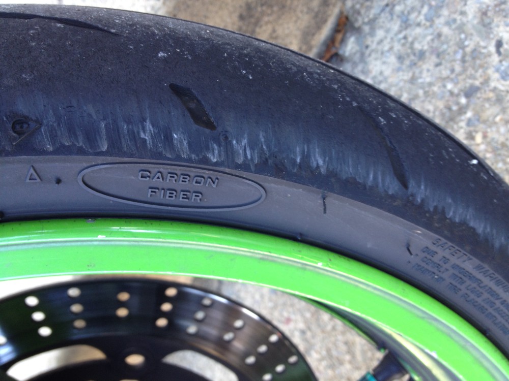
I hit a turn I do at 50mph all the time at 35mph on a cold day and for no reason lost the front end. Bike was almost flat horizontal in the turn, I was going down and crashing, and SOMEHOW the front tire held it’s grip and I made it out crash free. In fact, I haven’t related this story anywhere yet, and I’m going to post up what the tire looked like in the slide. It was crazy. (I examined the turn at great length. No ice, no water, no oil, no reason to have a slow barely leaning bike wash out on the front end. Only thing was there were a few lined up ridges in the corner – perhaps it induced a mini speed wobble – although the handle bars didn’t shake, the bike just nearly went down to pavement suddenly.) Can’t explain but it was crazy.
I wish I could understand what happened so I could learn from it and avoid it in the future.


Posted in Uncategorized by green
Valve Adjustment Kawasaki ZX6E How to, DIY, Step by Step Instructions
Hi all. Here are step by step instructions with pics for how to check your valve clearances and adjust them. I just finished this job. I also have a video for it as well.
Video of adjusting valves I made, click here:
Tools: Ratchet, 10mm, 12mm, 8mm, 14mm, 19mm sockets, ratchet drive extension, needle nose pliers or regular pliers if you don’t have that, phillips screwdriver, flathead screwdriver, feeler gauges set, torque wrench is a good idea, spark plug socket or 16mm deep socket, RTV sealant or equivalent Silicon sealant for valve cover portions. A strong magnet makes this much easier. An 8mm wrench is needed if you don’t want to pull your lower fairing off. Rubber mallet is good to have on hand to whack tightened items, Razor or a way to remove gasket material. Nitrile gloves and shop towels / rags are nice to have. I will update as I recall other items.
Parts: Spark plug O rings (the manual says to replace – I didn’t), valve cover gasket – I did replace mine as it was leaking oil. Often you can reuse them if in decent shape as they are resilient rubber.
You will need 7.48mm diameter Shims – assuming you have to make any adjustments, but you cannot know what sizes until you get in there. If your spark plugs are 10,000 – 15,000 miles on them or more you might want to replace those while there. NGK CR9E is the proper part for spark plugs.
There is a lot here on this post. It may look intimidating, but it’s not too difficult and much of it becomes very obvious when you are in there looking at it all.
Get started!
Bike must be stone cold, so it should have sat overnight without the motor running.
-Remove seat.
-Disconnect negative battery terminal
-Remove left rear fairing
-Remove fuel tank (disconnect one main fuel line, and disconnect fuel gauge wire). I learned a new trick here – use a pen cap to shove into the main fuel line to seal it while working on the bike.
-You may want to remove left or both middle fairings or neither one (I later took out my left middle fairing).
-You may want to remove your lower fairing. I did not.
-Remove airbox.

-Remove left and right ram air tubes out of the frame – you will need this clearance.

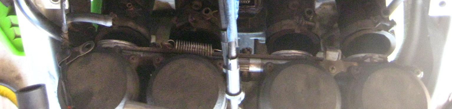
-Loosen carb mount throat band clamps and slide carbs out of engine intake boots. You can leave it just slid back, I did.
-Get any emissions tubes out of your way.
-Unplug the spark plug boots.
-Unplug ignition coil wires and move aside.
-Remove both ignition coils – unbolt their black metal mounts and take both parts out – you will need this clearance.

-I disconnected my choke cable from the carbs. Easy, you can lever the choke on, then push it back in while holding the cable to give it slack and it can come right out from the choke anchor point at the carbs.
I moved it out from the frame hole and routed it over towards the right handlebar – out of the way.


You can leave your throttle cables attached. They are a pain to re-connect so I left mine attached.
-Disconnect the motor plastic heat shield. It has two 10mm bolts that hold it in at the upper front part of the motor / valve cover area. Shove the loose heat shield as far forward and slightly up as you can (for clearance).
-Unbolt the four 8mm bolts holding in the pickup cover (middle right lower side of bike – round smaller cover in front of the clutch cover). I used a wrench on the upper front one without removing my lower fairing. Your mileage may vary. You may prefer to have easier access to bolt #4. 
-Unbolt the valve cover. It should free up where you can move it, if not very gently tap it with a rubber mallet.
How to get the valve cover out:
I shoved the main wiring loom up. I raised the right side of the cover up and diagonally pivoted the right side toward the rear of the bike and was able to finesse it out. There is very little clearance here, you will feel it hitting things below while trying to wiggle it out of there. 
Now you are looking at your valve train and camshafts and sprockets and chain.

-Back to your pickup coil area. Use a 19mm socket and turn the motor CLOCKWISE (only!) until the 1/4 T marks line up with the upper 12:30 / 1pm O’clock position raised up built in ‘indicator’. I’m pointing at indicator below:


Look at cylinder #1 area (far left of bike sitting on it). The lobes should be facing away from eachother and up slightly close to 40 degrees / 45 degrees. If they face in, or cylinder #4 lobes are facing away from eachother, you have #4 cylinder at TDC. See here how #4 cylinder is at TDC.


Rotate the crank again at the pickup coil cover area a full 360 degrees which will put #1 at TDC.

The above green arrow is pointing to the #1 lobe facing out or away from eachother. (Arrow is not directional sign).
You can now measure your valve clearances. There are 16 to check. By setting #1 cylinder at TDC you can check all (4) valves of #1 cylinder, plus the exhaust valves on #2 cylinder, and the intake valves on #3.
Insert your feeler gauges between the camshaft lobe the the inverted shiny bucket below it. I am checking cylinder #3 intake valve while #1 is at TDC:

Feeler should have a slight drag on it but if you have to force one in, it’s the wrong size. Use the smaller number in that case. Write down each measured value for each specific valve. I made a rectangular chart with EX and IN tables and 8 boxes for each valve. Write down the numbers with something like that to keep track of each one. This is very important if you need to adjust your valve clearances. You must know all this information.
There are different spec values for the EX and IN valves. Clearance specs for our bike are this range:
Exhaust (EX): .22mm – .31mm
Intake (IN): .15mm – .24mm
Rotate the crank again at the pickup coil cover area a full 360 degrees which will put #4 at TDC. You can measure the clearances of all of #4 valves, the Intake valves on #2 and the exhaust valves of #3.
(You can also spin the crank again to the 2/3 T lines and check all 4 valves on one of the #2 or #3 cylinders if you like. It’s the same idea: as long as the cylinder’s Intake and Exhaust lobes face away from eachother and slightly up you have that cylinder at TDC and can measure the valve clearances for that cylinder).
If any of the valves are out of spec you will need to swap shims to alter the clearance to within spec.
If everything is within spec pat yourself on the back, you are done. Reassemble and go ride!
However, you probably will find valves out of spec if you waited awhile like me.
To remove the camshafts and to change shims and alter your clearances:
At this point, you actually want to have #1 cylinder at TDC. Recall if the indicator is at 1/4 T mark, either #1 or #4 could be at TDC right now.The manual glosses this over point, that either #1 or #4 could be at TDC just by lining up the 1/4 T mark.
Put #1 at TDC! If it isn’t (which way are lobes on #1 pointing – inward then #4 is at TDC), so turn the crank bolt at the pickup cover another full revolution back to 1/4 timing marks. This will now put cylinder #1 at TDC (#1 lobes are facing away from eachother right?).
The reason you want #1 at TDC instead of #4 is because the timing marks are much better and easier to understand and line up on the #1 TDC marks on the camshaft sprockets. Do not move the crank again once you’ve set it to #1 TDC and have started below procedures – Important!
Now look at your camshaft sprockets.
The rear one is the Intake marked IN, and the front one is the Exhaust camshaft marked EX.
You should see the IN — line at the rear of where the valve cover meets the head and the EX — line at the front of where the cover meets. They should be evenly horizontal. Below is the IN camshaft with factory line at the cover / case split:
Now count the links and / or rivets between those horizontal marks. My bike had the timing marks in between whole links. The book mentions links split the lines. Either way, use logic / math, the two lines should have 17 links between them and 34 rivets. If your marks are like the manual, you have 16 links and (2) half links between the marks which also equals 17 links (and 34 rivets).

NOW MARK your camshafts – both, and the sprocket with a line. THIS IS VERY IMPORTANT. I have written that in ALL CAPS, like I am almost shouting. It’s that important.
Skip this, forget this, and you have made more work for yourself and stress.  Make sure to mark them well. I used a metallic sharpie and that wasn’t the best as the marks nearly wore completely off from handling the chain. Paint pen / paint is best. Mark lines across both the chain and sprocket for timing alignment marks.
-Remove the CCT (Cam Chain Tensioner). It’s located under and in front of the carbs. I’m pointing to it.

-Remove the center bolt (12mm) first. This will release an under pressure spring and pin and copper washer with the bolt. Place aside.
-Remove the two outer bolts (10mm) now and remove the CCT housing from the engine. I had to whack mine with a rubber mallet, it was stuck in there pretty good. It popped out with some energy.
Now the camshafts have what’s called caps on top of them, big machined blocks of aluminum holding them down and inline (we could abbreviate them as Al Caps, haha).
 Look closely at the 16 bolts. They have little numbers beside them.
 Start to loosen the bolts a turn at a time in the order starting at #16 to unbolt (you tighten on reinstall starting with #1).
Do Not loosen the entire bolt. Just a little at a time to start until all the pressure has been released from the camshafts. If you don’t do it this way you won’t be able to get the caps off due to pressure misalignment.
You may want to remove the spark plug O rings here. At least be careful they don’t fall off and down into the motor:


Once the caps are off – again Do Not move the crank now again until the job is nearly finished!
When you remove the camshaft caps, be mindful there are 4 locating dowels in between the camshafts. They may have come out with the caps. Make sure where all 4 are, and that they are not missing or fallen down into the motor. They also have 4 very small O rings around them. I left mine in place as is (see pics). I ALSO left these lower spark plug O rings right where they were. This is where the manual insists to replace them. Anyway, I didn’t so there you go.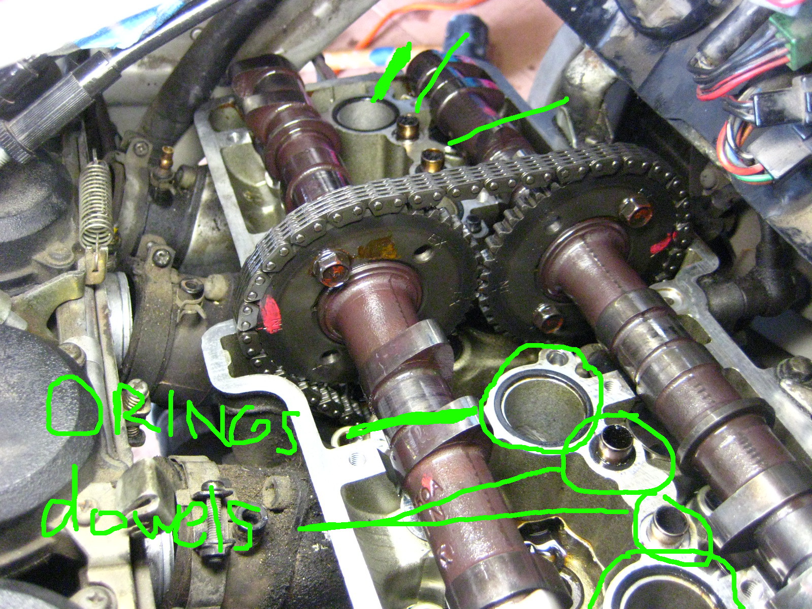
Next, You can in fact remove the camshafts without unbolting the sprockets like the manual says to do. You can move out the IN camshaft and sprocket together first and set aside.
 Have something right on hand to tie up the timing chain and keep tension on it so it does NOT come out of the teeth of the crank down below in the motor. Remove the EX camshaft and tie up the chain not letting the chain fall / drop / slacken much at all.

I used the throttle cables to tie the chain to.

With your camshafts out you have now exposed your buckets, the shiny metal round things upside down on top of your valve.


You need to remove the bucket and shim for any valve that was outside the factory spec value. You can leave in ones that are within spec. I had 14 or maybe 15 out of spec so I just pulled them all.
 The shim is stuck under the bucket in the above pic. Those shims are small! Like a small watch battery size.
I used a very strong magnet to remove them easily. With a strong magnet the shim should also come out at the same time under the bucket. Place the magnet center of the bucket for removal of bucket and shim together.
Take them out one at a time and put them in specific labeled spot for each valve. Each shim is different thickness if the valves have ever been serviced and it’s imperative to know which came from which for measuring. I used an egg carton and half dozen egg carton and marked one side IN and one side EX and put the buckets and shims in there to know which was which. 
So now you need to measure each shim that came out for any valve clearance you need to adjust and write down the precise thickness of them for each specific valve to tour table. Record final values in mm / metric as the charts are in metric as are the shim numbers for ordering.
So there are going to be a few figures for any valve clearance you want to adjust:
– Measured clearance
– Measured shim thickness
– Desired clearance
As the clearance are a range of values, you just need to get in that area. I opted for trying to make the valves all on the looser side of the spectrum as they will tighten with miles.
Then you can consult the Kawi manual lookup chart to find out what size shim you need to replace them with.

Write numbers down on paper, etc… I used a little whiteboard. The shims that are calculated to go back in are sitting on the board.
You can mix and match and replace with existing / used shims. You likely will find at this point you may have to go get certain specific shims that you need.
Basically the way this all works is, that generally the valves tighten up with mileage and the clearances lower / tighten. To get a larger clearance you need to get at thinner shim.
So if a shim that came out was measured at 3.00mm and your clearance was say around .20mm too tight for the spec you want, you would in this case replace it with a 2.80mm shim.
How about a specific example from my bike?:
On Cylinder #1 I measured my left exhaust valve at .038mm (way too tight!)
Spec for the exhaust is range of .22mm – .31mm
The shim that came out was a 2.95mm
Chart lookup value calls for a 2.70mm shim
New clearance once installed measured a .279! Perfect, the high side of the clearance range.
If you check some math there, the difference between the old and new shim 2.95mm and 2.70mm is .25mm
.25mm added to original measured clearance of .038 = .288 very close to the figure I got above. This is how it works. (in my case the .038mm feeler gauge could barely fit in between the lobe and bucket but it was the thinnest one my set came with).
You can calculate it yourself or use the chart. I used the chart to start, and then re-did all the math myself several times to make sure I was getting what I needed. I did not want to do this twice.
Once you have it all figured out (my first time – I took hours writing and calculating I think), get your new shims and install them in the proper valve spot. Then re-install your buckets. I kept my buckets stored and back in with the exact valve it came from.
Once they are all in it’s time for reassembly.
-Make sure your crank is still at 1/4 T mark.
Lubricate the bearing spots that hold the camshafts with motor oil. Or make sure they are still oily from before at least.
-Place your EX camshaft in first and line it perfectly back up with the link on the chain your mark meets up with on your sprocket. It will make this a fairly taut fit against the chain (and the crank below). That’s good.
-Install the IN camshaft next.
OK so here’s where you can toss some manual sh*t out the window. It states to have the camshafts in perfectly and flat down so that the IN — and EX — line marks are perfectly lined up with the case line and no slack on the chain. Yeah, good luck with all that. You’d need a circus strongman and or about 6 hands to shove the camshafts down on top of some resisting valve springs and hold it all perfect… plus it’s a waste of effort and time.
Think about it, the only thing that moves those sprockets is the chain which is only moved by the crank below. Even if there is some slack or not perfect lining up of the IN — mark and EX — mark on the case line, it will align itself.
JUST MAKE SURE your sprocket and chain link marks are perfectly lined up on both. You made those marks right? And that you never let pressure off your chain – and therefore let it slip off the crank sprocket deep down below.
Have the front EX camshaft tight-ish is nice (doesn’t have to be) and let the IN camshaft go where it’s going to go – it won’t be perfect. There will be chain slack between them. That’s ok, it’s all gonna fix itself.

If you removed any of the 4 locating dowel reinstall them and make sure the small O rings are around them. Also if you are replacing or removed the lower spark plug O rings, put them all back in now.
Now re-install the camshaft caps starting with #1 bolt. I tightened each one until there was resistance and then went slowly a little at a time in order #1 – #16. This will flatten down the camshafts. But don’t worry they are off yet. DO worry and make sure the chain doesn’t jump off either sprocket’s teeth.
By tightening down the caps, they will likely rotate and move around your camshafts a bit like how it happened to me below. This is ok, just Make Sure your marks are still lined up, and that there is the 17 links between the horizontal marks on the sprockets. 

-Once the caps are tightened to 12 NM (104 inch/lbs) of torque, YOU MUST reset your CCT. If you put it back in as it was you will likely break something and cause damage. Reset it.
You do that by pressing in the little button and then pushing back the little “plunger” (foot thingee) back into it’s holder. I’m pointing to the ‘button’ you depress to push the plunger back into the housing.
This pics shows the ‘plunger’ retracted after resetting it:

-Now re-install the CCT housing, the raised arrow on it aligns horizontally at the top (but not pointing ‘up’).
-Bolt in those two 10mm bolts on the housing.
-Reinstall the bolt, copper washer, pin, and spring into the CCT housing. It will be tad difficult as the spring will push back on you, but get the bolt in and tighten to 9.7 NM.
This will now engage the CCT to put pressure on the chain.
Make sure your painted on marks are all lined up and you have that 34 rivets / 17 links between the sprockets IN and EX lines.
-Now go turn the crank clockwise: Most likely you will see the slack between the sprockets go away instantly!
The chain will pull both camshafts where they need to be. Before turning crank:
After turning crank:
-Rotate the engine many revolutions to set the shims and make sure everything feels normal and sounds good. If you messed up the timing now is, well, the time to figure that out. Any major resistance stop! You may be mis timed and forcing valves into pistons.
-Now you will re-measure your valve clearances and make sure they are all within spec. If they are not – you know what you’re doing next. Figure out which ones are off, figure out the proper shim, and get it / swap it in from spares once you’ve taken the caps off again and the camshafts out. Hopefully you’ve gotten it all right and won’t have to do this (I did not have to).
If you have gotten them right – congratulations! You owe yourself a beer tonight.
So time to re-install it all.
What I did was turn the motor several times by hand to make sure it all felt right and then re-installed the pickup coil cover. I cut my own gasket for it as the old one was toast on removal.
-Then reinstall your valve cover and gasket. Make sure to use sealant on the (4) lower half moon cutout parts of the gasket – I used hi temp RTV silicone sealant. I got my cover wiggled back in less than one song on the radio – it was finesse-y but not too bad. I moved the wiring loom up a lot and slid it back in under the left side first.
-Reinstall the valve cover bolts and torque to 9.8 MM (87 inch/lbs).
-Re bolt in the black plastic heat shield
-Install the spark plugs.
-Install the coils and mounts back and the spark plug boots.
-Re connect the ignition coil wiring.
-Re install your carbs into the boots and tighten the band clamps.
-Reattach your choke cable to the carbs.
-Re-attach the negative terminal of the battery.
Now at this point I decided to test fire the bike. I had fuel still in the fuel lines and carbs so I fired it up with the tank off. It cranked a little as I had the choke in wrong position but fired right up and sounded great!
Then reassemble the rest of the bike.
-Reinstall ram air tubes.
-Reinstall airbox and then all vacuum lines and hoses.
-Reinstall the fuel tank and fairings.
Congratulations! Go ride!
This was my first I4 motorcycle valve adjustment. (I’ve done my 16 valve car before and an 6 valve inline twin Honda motorcycle – that was cake). It’s not a really difficult job, I just got agitated when I could not get any feeler gauge to go into the exhaust valves on cylinder #1 and #4 (because they had tightened to zero clearance and I did not know that yet) and a few things in the manual were not clear and an item wrong.
A weekend timeframe would be a good time estimate if this is your first time and you are somewhat handy in the garage. You likely have to factor in getting certain shims. You might be able to get this done in a day. But you will feel really good about getting it done and probably take half the time next time.
My motor sounds better, starts way better than it ever has since I’ve owned it, I have better low end power. I had 3 exhaust valves at zero, or less than .038mm anyway, clearance. I was risking burning a valve and probably had lower compression and power as a result. I was pretty thrilled to get this done.
Posted in DIY, repair and tagged adjust valves, clearances, DIY, DOHC, how to, i4, inline four, Kawasaki, Ninja, Valve adjustment, valve clearances, Zx6e, zzr600 by green
Valve adjustment a total pain in the ass
Mileage: 60,400
I cannot say I am enjoying this particular job.
Firstly I wasted several hours lining the timing marks up wrong. My digital Haynes copy timing mark photo is completely illegible. And all I could find online was ZX6R and other Kwawk instructions so I thought I was supposed to line up
1/4 and 2/3 lines with the split in the cases – horizontally. Not the way.
This (apparently) is the way that I had to sort of figure out myself:

My clearances are really bad. 3 valves are at minimum on the gauges – I can’t even get the thinnest one at .0015 ” through. And I’m irritated that the engineering seems to assume you have dwarf lady Japanese tiny hands. I can hardly move my mitts around in there. Pain in the…
I cannot see how the hell you are supposed to get any gauge to go through the exhaust lobes of #1 and #4, especially the farthest outside ones. It’s ridiculous. I guess I might as well make up some numbers.
My exhaust clearances are in inches:
Exhaust:
.0015, <.0015, .005, .003, .006, .004, .005, and zero or <.0015 Intake: .005, .005, .006, .005, .0055, .007, .003, .004 So it looks like I have exactly ONE valve in spec @ .007 and it's on the tight end of the spectrum. Not good, I guess, very not good. Been on this all day, and haven't even gotten to pulling the camshafts out yet to measure what shims are in there. ---- And now (Sunday) I got all the old shims out, and calculated the new ones which took hours to be sure. I had to drive to town twice to get them as I made one error. I put the cams back in, and the timing chain looks all slacked wrong, so I am worried about this:
—-
Wednesday WOOHOO!
Fired up bike and it sounded great!
I then finishes installing the air box, hoses, tank and fairings and hit the starter again several hours later. It started so fast it kind of shocked me. It’s never started so instantly. Also I can go off the choke now very quickly and it idles nice and smooth.
I also installed the replacement ignition coil set that kjfire4life sent me from North Carolina several months back. New NGK CR9E spark plugs also installed. The original set I put was back at 43,400 miles so they’ve lasted a good while.
Very very psyched today to have this done! And I did not have to pull out the camshafts again and try to rotate them or get rid of the slack. The CCT tensioner and the crank turning and pulling the chain straightened it all out instantly.
Posted in Uncategorized by green
Debaffle stock exhaust Kawasaki Ninja ZX6e. Exhaust Mod. How to. DIY
This is a modification to the stock dual can muffler exhaust on the Ninja ZX6E 1993 – 2004 also known as the ZZR00 in 2004 and in Europe.
This was all inspired by “mechanicalmadness” member of the old zx6e.com forum. He did this exhaust mod and made a great write up although it’s gone from the internet now.
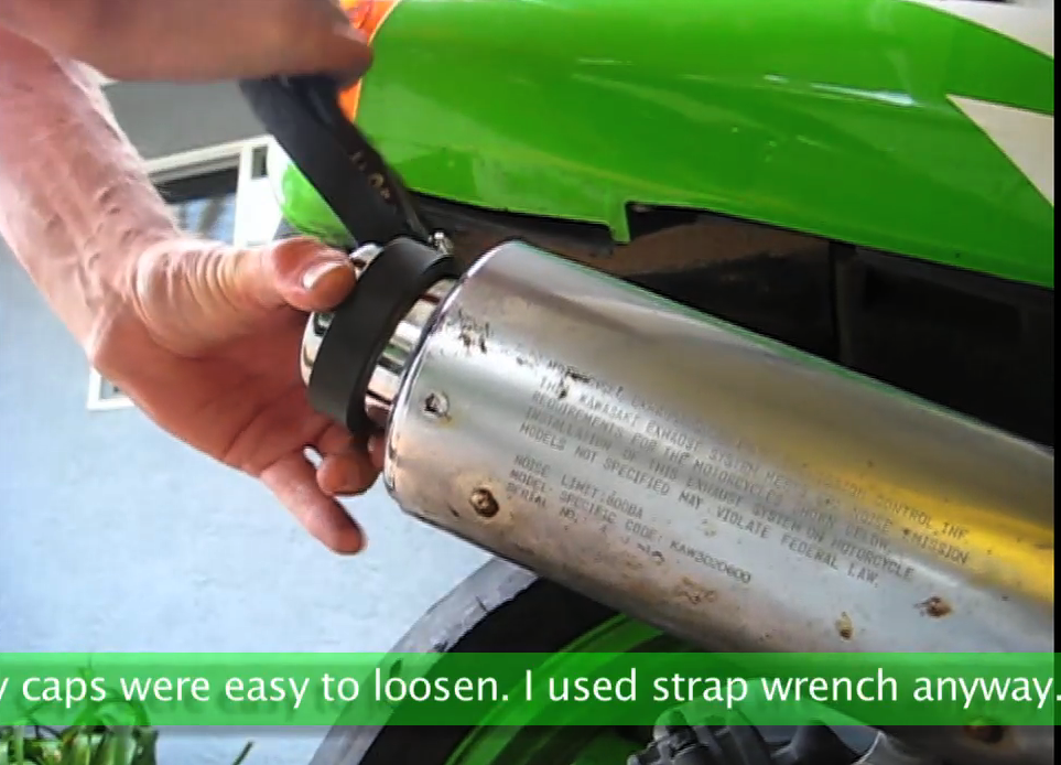
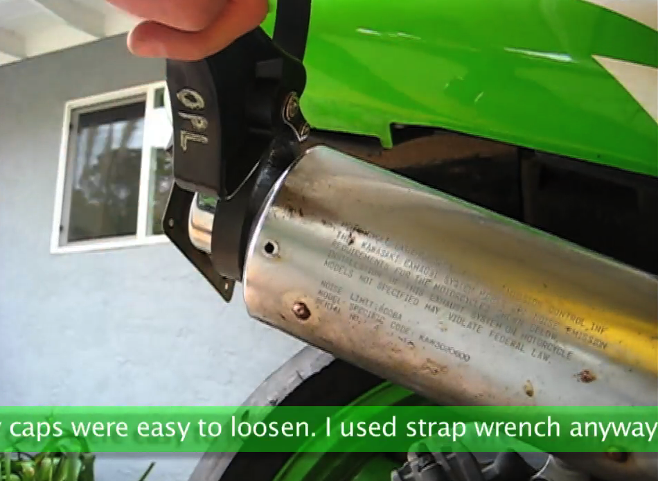
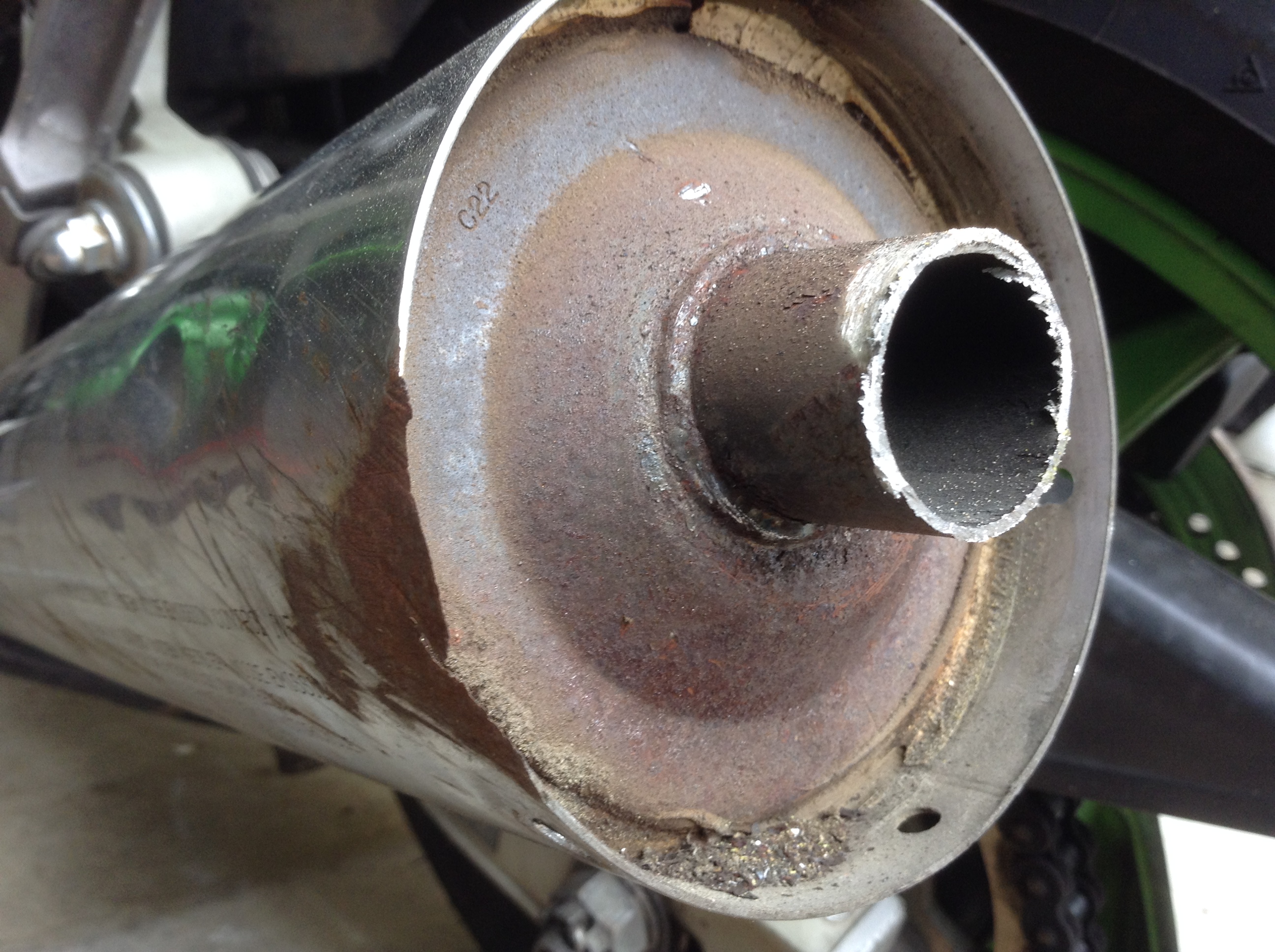
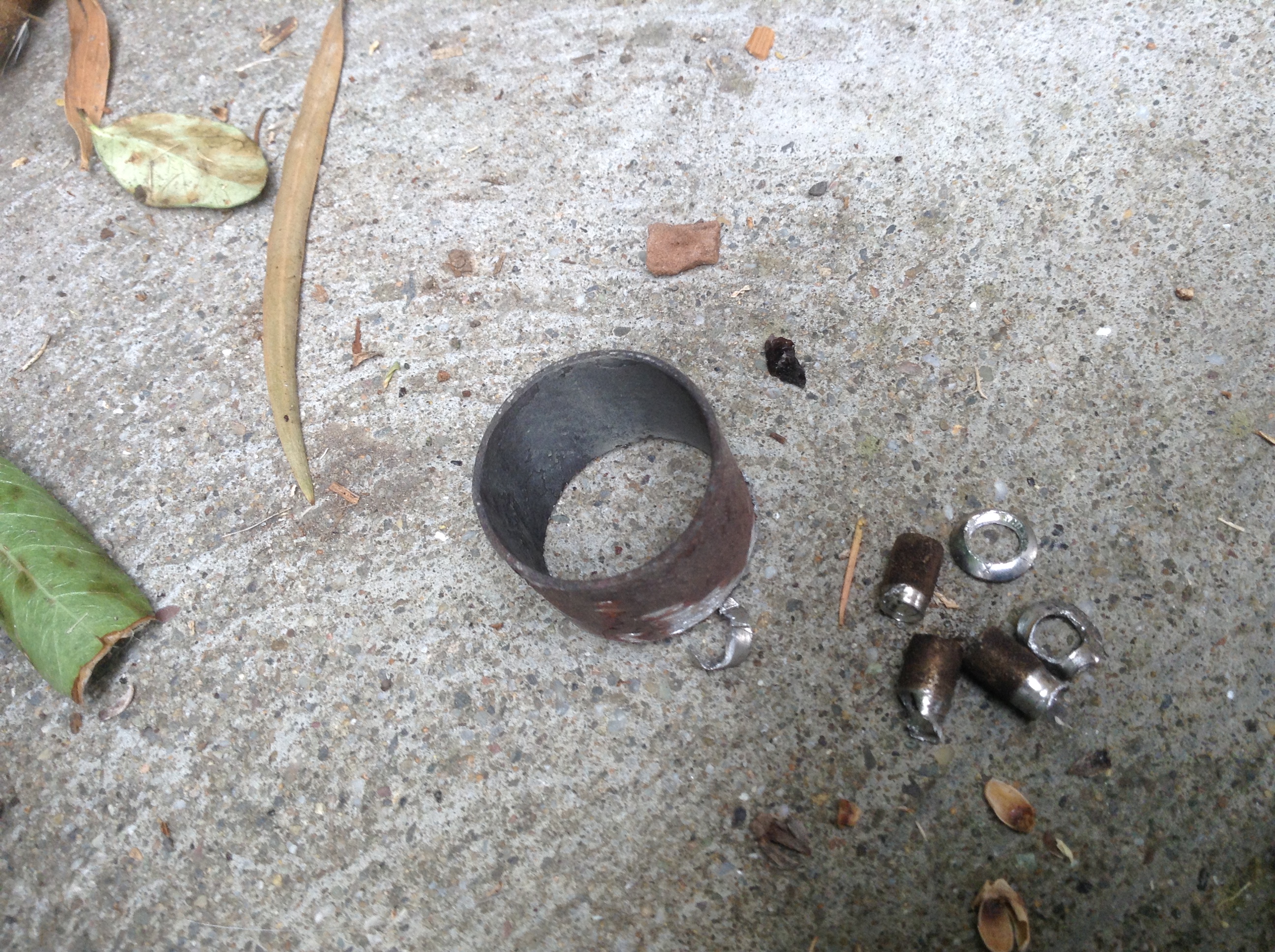
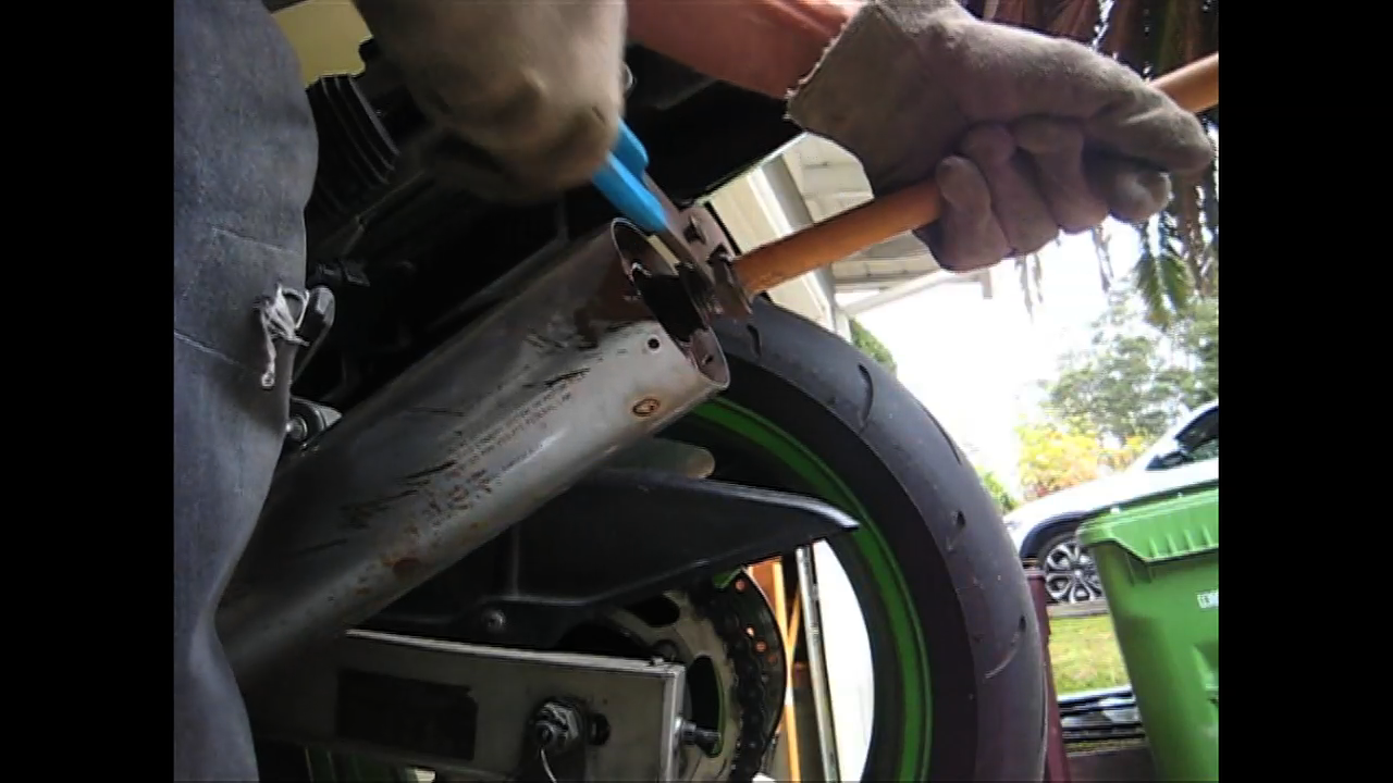
First thing, you have to drill out the exhaust cap rivets, there are three per side.
Next, you need to spin the exhaust caps out. I used a strap wrench. There is some sealant in there that does not let the cap release easily. Mine were easy to loosen though, perhaps due to their age.
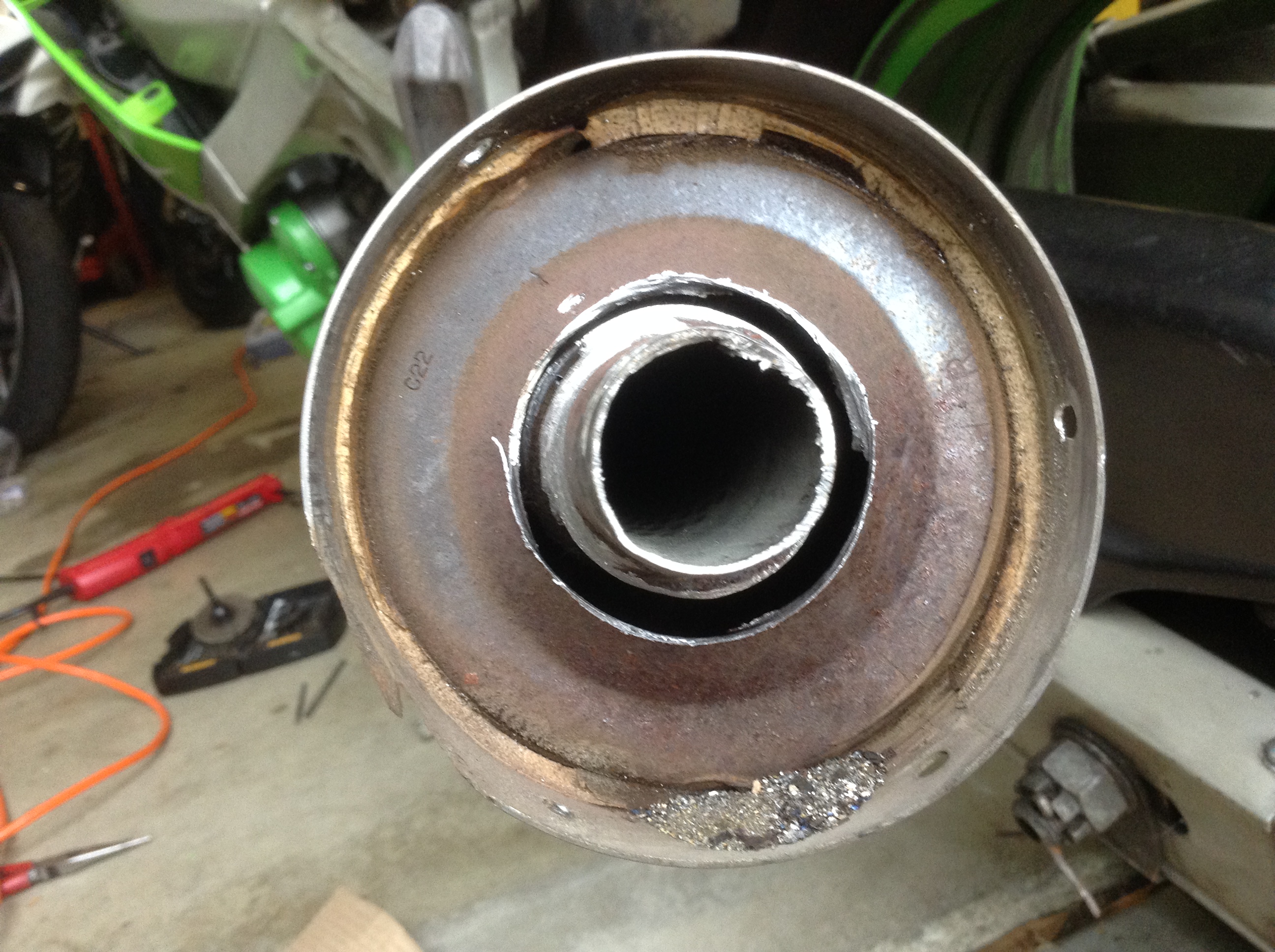
Removing the end caps reveals this:
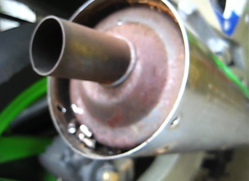
This is the final tail pipe that comes from 1 of 4 pipes inside as you are about to see.
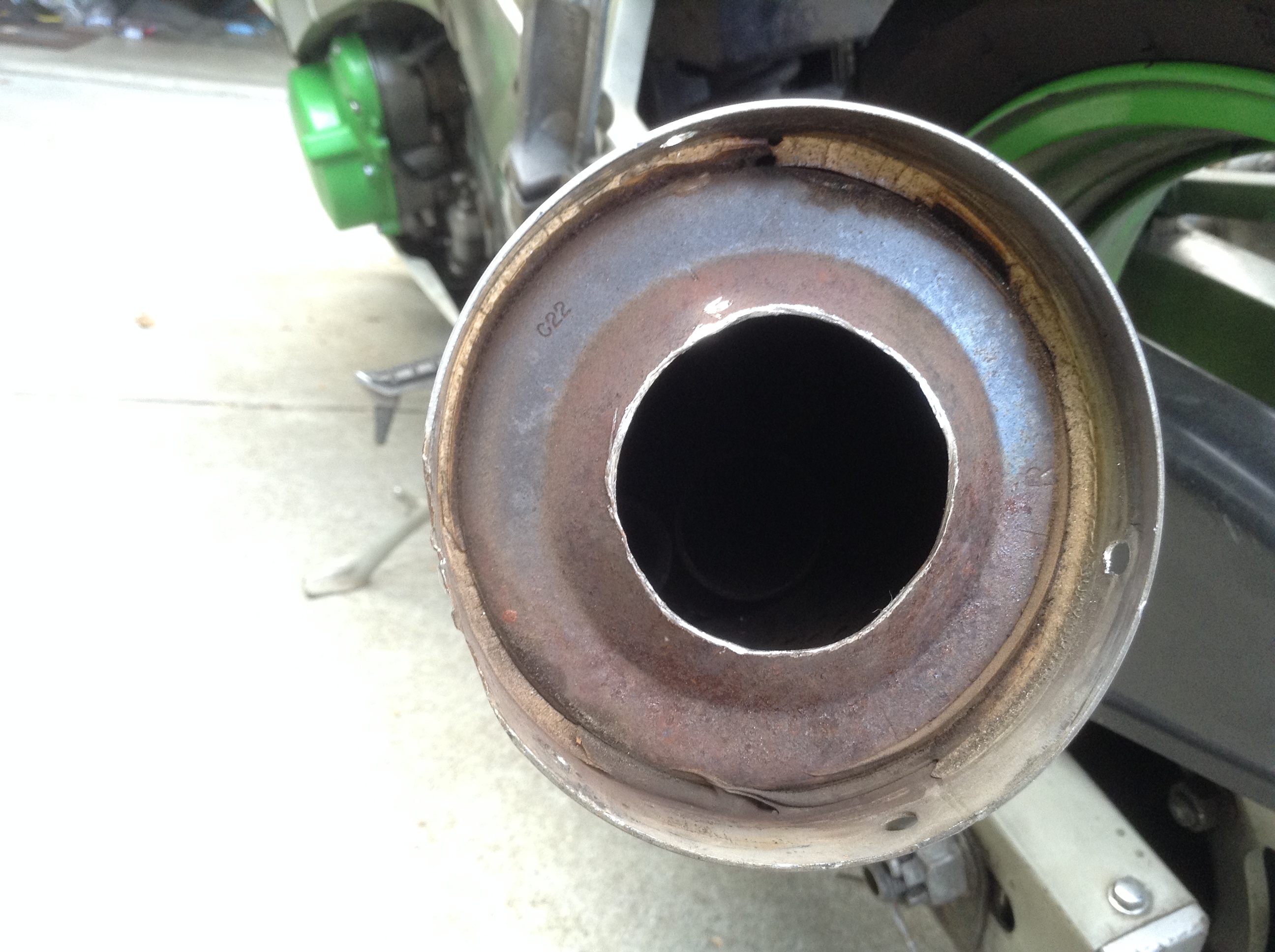
Then, I used a 1 + 3/4″ (44mm) hole saw for metal to make it fairly easy.
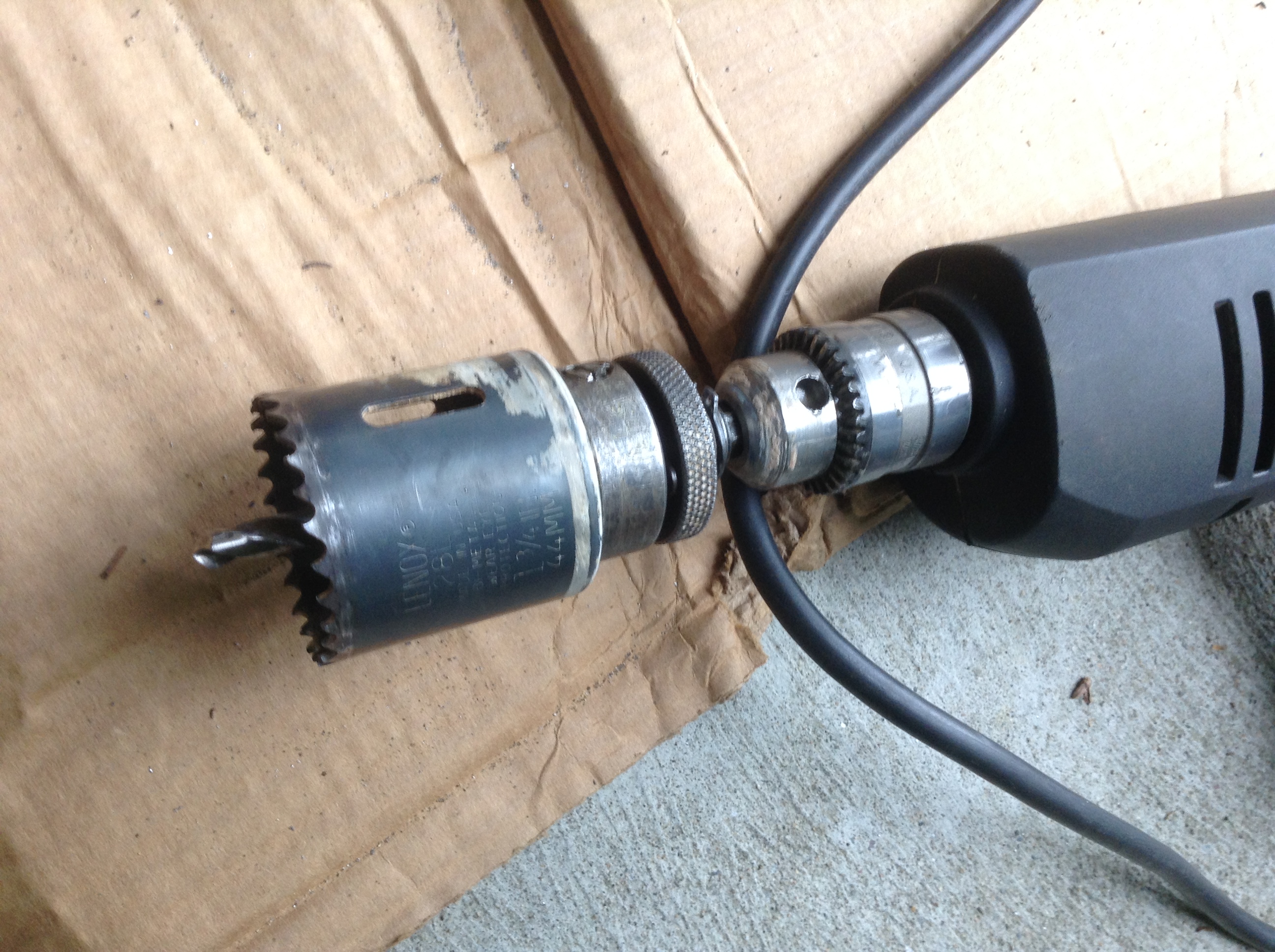
To get the holesaw to bite into the base of the end of the exhaust I cut the tail pipe off with a hacksaw first – maybe 1.5″ off or so.
Then the hole saw will easily reach the metal to cut.
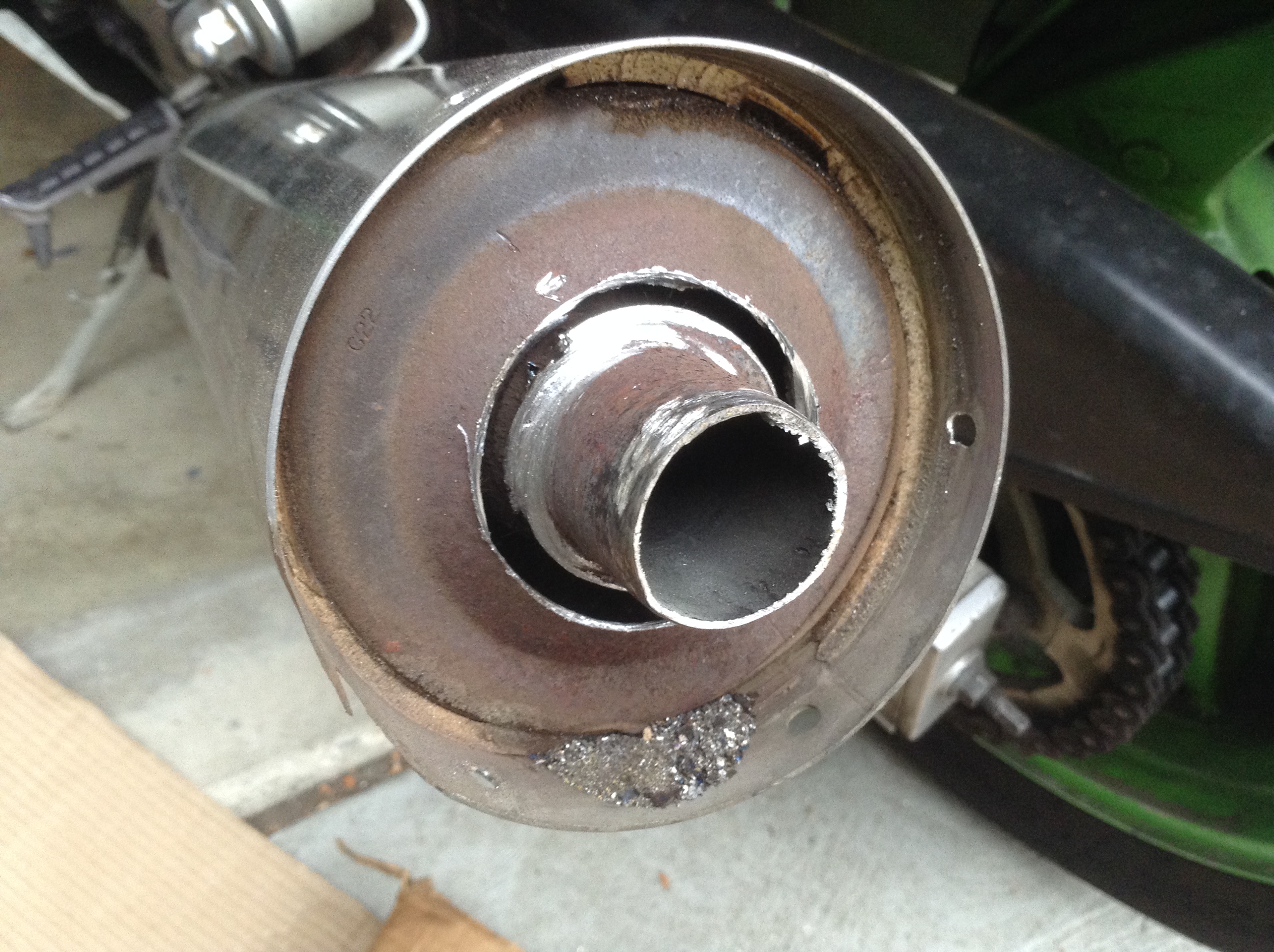
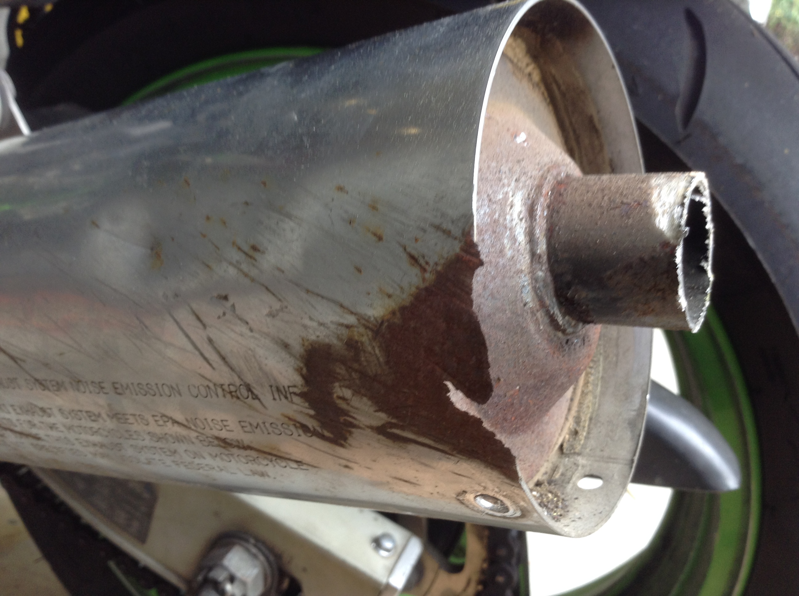
Once that’s done, you now need to break the inside weld spots on this tailpipe / baffle. I jammed a wooden dowel in there, and used lockjaw pliers to put a lot of force on it, mostly rotating. You might find this step easier with a larger hole saw hole, but I didn’t want to go too big here.
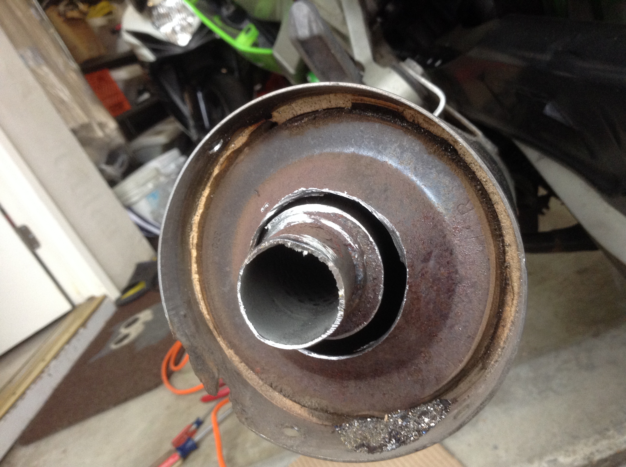
It took some time but eventually you fatigue the metal and snap it off and out of there.
You can now see the insides of the muffler. You are looking at the plate of the middle chamber.
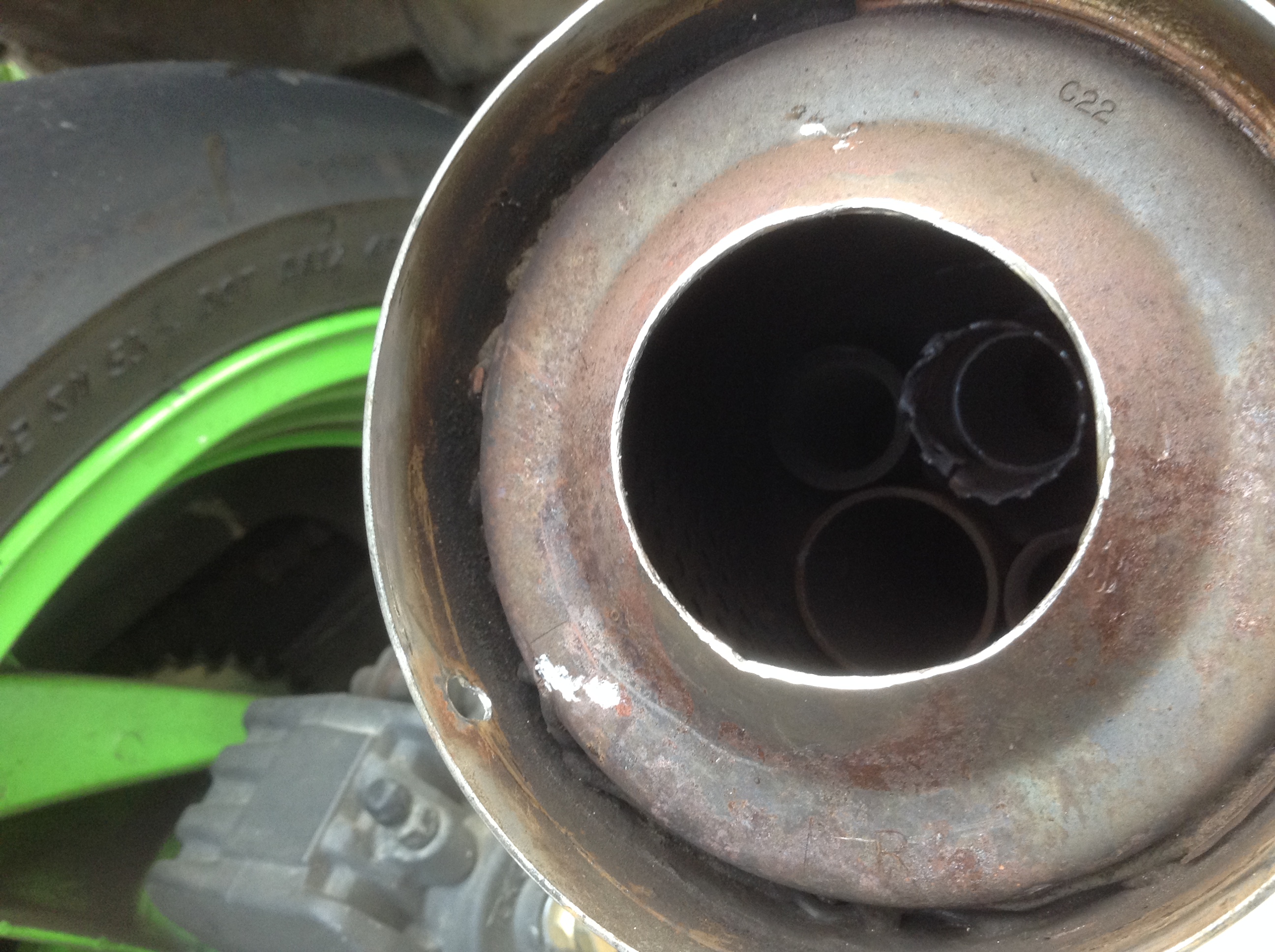

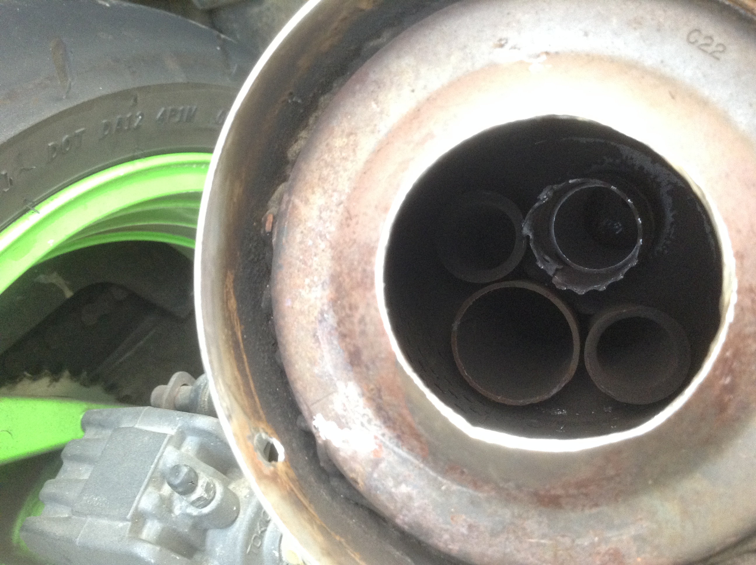
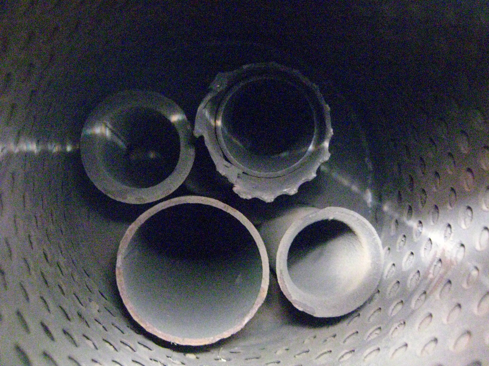
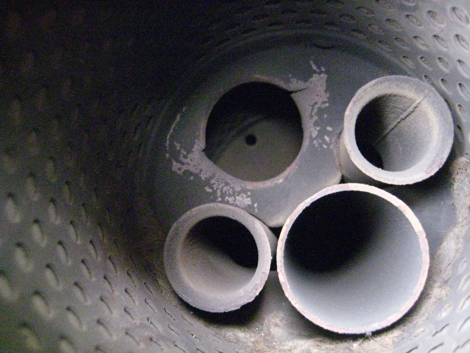
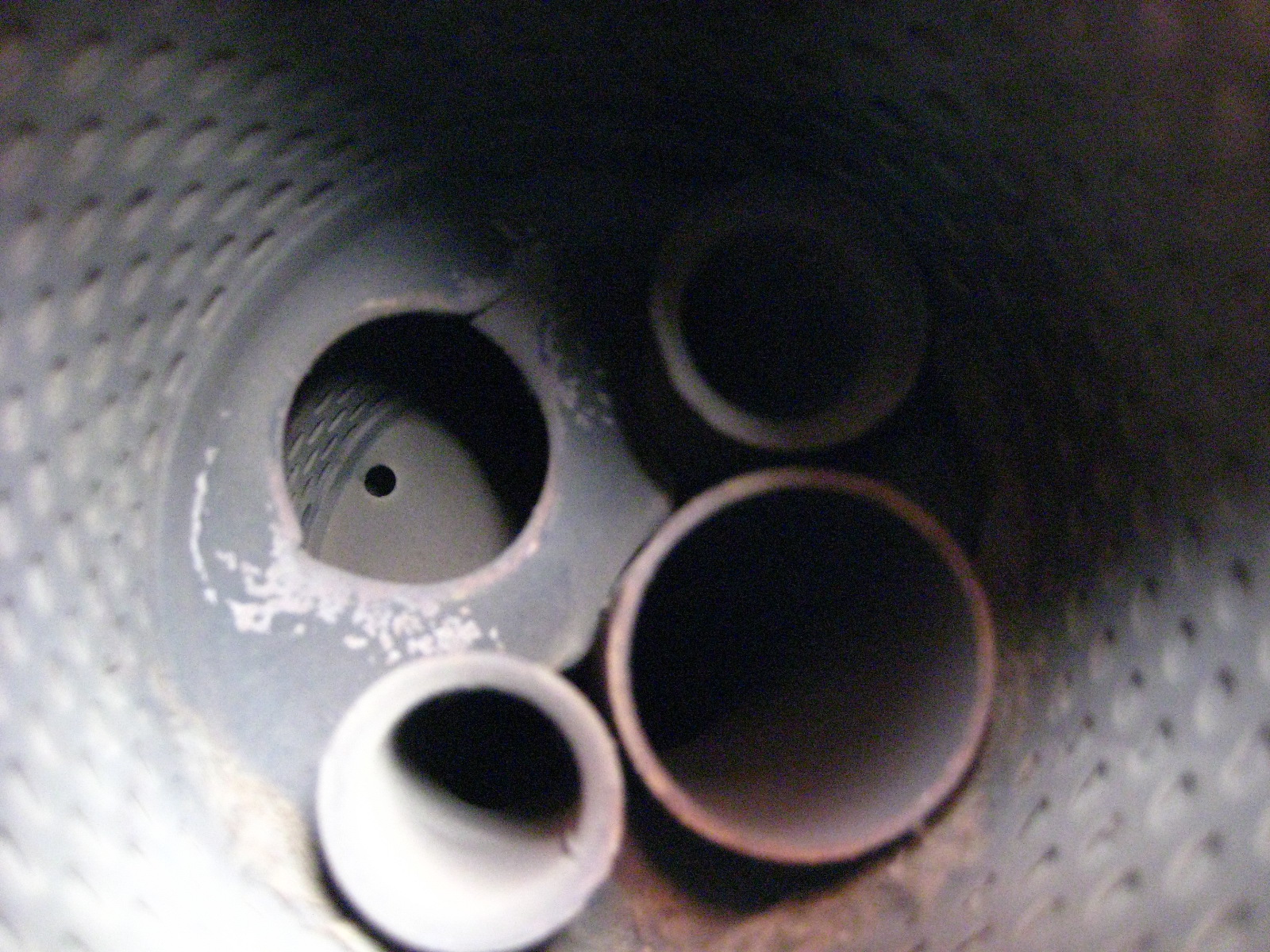
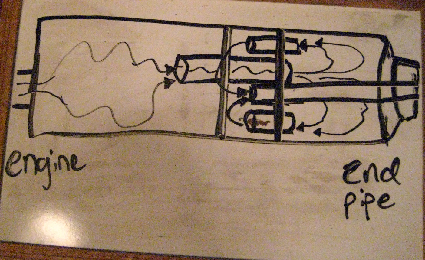
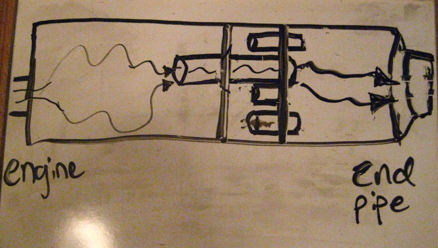
These exhausts have 3 separated chambers. What this mod does is effectively eliminate the middle chamber AND cuts out a large back and forth pattern the exhaust gases used to have to follow backwards into the middle chamber and then out that small final tail pipe / baffle. With it gone, the gases enter the first chamber and then exit out the larger diameter pipe, bypass the middle chamber altogether now, and then exit into the rear chamber and have free outflow out the back now.
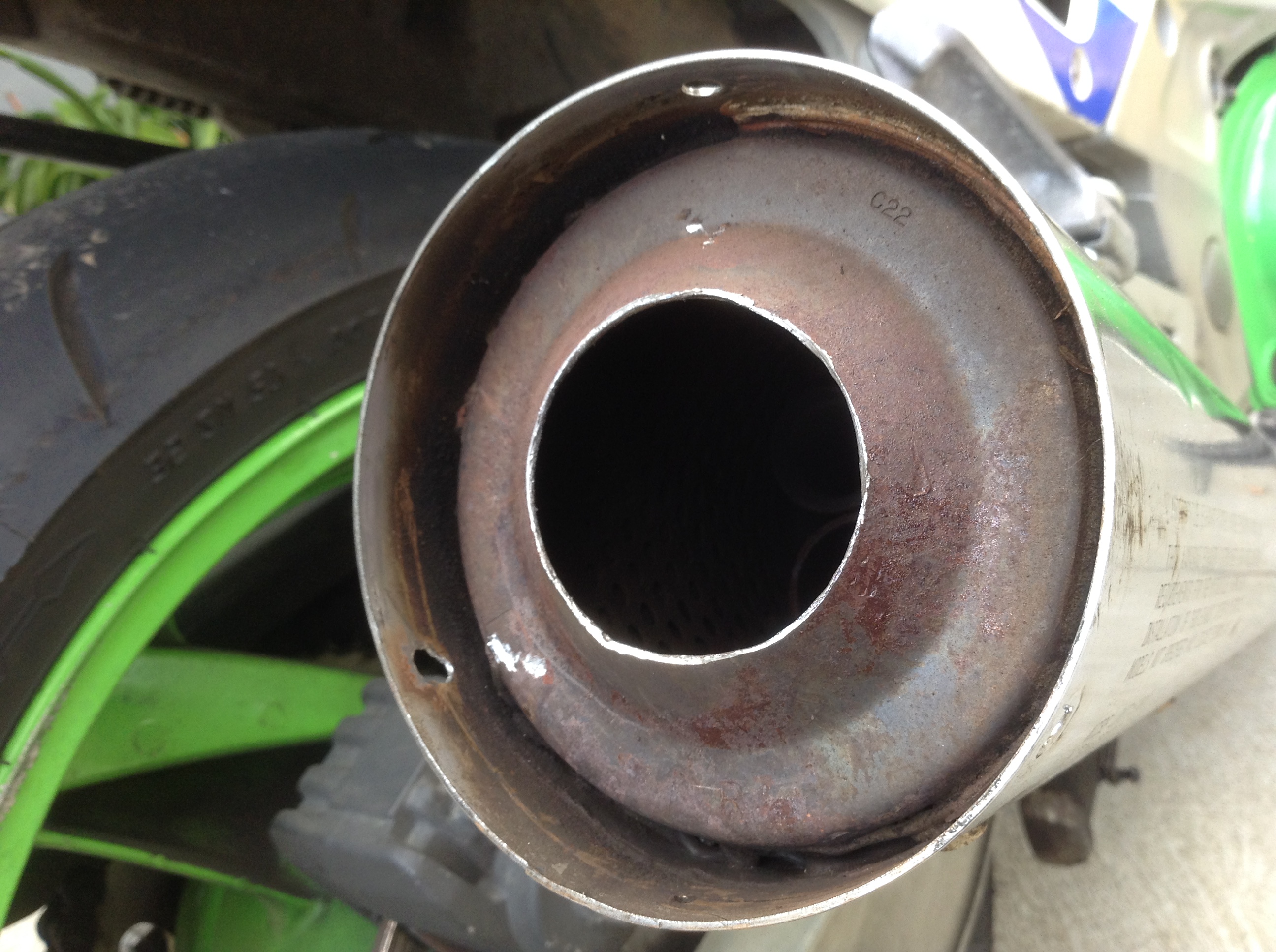
Before:
After:
Here is a photo of an ‘exploded’ stock muffler:
Yo
Result?:
It sounds SO much better than stock. Idle is amazing with a nice throaty burble. Cutting this all out rather than drill holes around the end tail pipe makes it deeper / bass-y sounding, and not raspy at all.
Depending on load and throttle position etc… it can get a little loud and drone starting as early as 3500 and through 5000 rpms. Again, depends on several factors. By 6000 + the exhaust sounds sweet and great!
My bike idle smoother at lower rpms with this as well. It burbles nicely, it really sounds fantastic.
This little mod has totally changed the feel of the bike. It was such a quiet bland exhaust before. Some people have done this and found it too loud for them.
I have worn earplugs riding for the past 2-3 years to protect against hearing loss (from wind noise), and I LOVE this exhaust with my ear plugs in. I am also noticed more by cars driving around as they have more of an audio warning I am nearby.
I will posting a proper comparison of the before and after video with same video gear with the same manual settings so you can hear the difference.
It’s a free exhaust tone modification and I did it in just a few hours on the weekend. Enjoy!
Posted in DIY, repair and tagged baffle, chop, debaffle, debaffle cans, debaffled, exhaust, exhaust mod, Kawasaki, muffler, Ninja, stock exhaust, Zx6e by green
Just debaffled my exhaust. ZX6E exhaust mod.
Mileage 59982
Custom modified my stock exhaust. It took a little over 2 hours. I shot pics and video of the process and will upload a YouTube video of it soon.
I also installed a new 5/16″ Parts Unlimited polyurethane fuel line. The main line to the fuel filter and filter to pump runs.
I installed a new WIX 33011 fuel filter while in there. The old one was in there for 3 years and maybe 16,000 miles so time for a fresh one.
On startup… Wow this thing is loud. Kind of annoying me loud. It also made a huge after fire POP noise on startup. But it idled immediately at 1500 rpm cold with the choke – it’s never done that.
When I got it warmed up, it sounded pretty good at 1500 idle. And shutting it off and re-starting it warm, it sounds pretty cool.
But I will say at 5000 rpm it’s loud. 6000 rpm is the old 9000 rpm noise level I’d say.
I’ve been very curious to try this out for a long time. I commute and lane split more than I’d like and I have been thinking this could be better to alert cages I’m coming up the lane.
I used a few bits to drill out the 3 exhaust cap rivets. Then I used a strap wrench to spin free the caps – although they were close to a bit loose and did one by hand. I took a hacksaw to the skinny outlet pipe there for the next step: Then I used a 2″ metal hole saw to cut a 2″ circle out of back of exhaust around that small pipe. Then I wiggled and man handled and broke free the rear baffle tube so it bypasses the whole last chamber and three tubes it no longer needs. That part was the most tedious, although not terribly bad.
Kind of interesting overall.
Have no idea what it will be like at speed or the highway… But I will find out tomorrow on my commute!
I wear ear plugs all the time anyway, so I thought this might not impact me as much as others.


Posted in Uncategorized by green
Mini Rt 1 tour, Pescadero lunch after work, Pacifica
I was done with the main part of work at 11am and riding from work at noon on Friday!
Decided after four day work with a double up job on a special day it was time to celebrate a little with a joyride to the coast and along it in the sunny weather.
Just before La Honda small center I hit up some sweeping turns and looped it there about a dozen or more times. Was a rush, trying to get the knee down on these huge turns. Didn’t but it was fun!
I stopped at Applejacks hoping to get lunch, but it was close to empty and they have no kitchen apparently. So continued on out of La Honda.
I took a new road for me, up past the Jones Gulch YMCA and eventually got on the windy mtn pass road direct to Pescadero.

This was my third day using my brand new Shoei helmet and I’m really loving it. Very solid feeling, close to air tight and quiet.


Very pretty riding through redwoods and nice twisty roads.


Stopped there for a (late) nice sandwich at the General Store and had a little conversation with a cute girl there from out of town.
Out to the ocean and Pescadero State Beach. I really love the Pescadero area. I dream of living on a ranch there, apparently everyone else does, I saw a house for sale for $1 Million.

I always like to stop at this one overlook at take a picture:

Along the 1 up through Half Moon Bay and Moss Beach. I stopped at the Moss Beach Distillery here just to see the beach in the daytime there (only been there once at night).
It was a beautiful beach view up some small cliffs. I walked out to the peak of one cliff, and found out later it was all restricted. Was kind of funny because there were tons of people around and Distillery staff and no one said a thing to me. Took a few ‘illegal’ pictures there I guess you might say.
There were humpback whales spouting out in the ocean.


I tried to find that beach overlook and wound up on California street and down to a little beach park there that was quite cute and I plan to go back to on a warm day and enjoy the beach there.
Onward toward Pacifica, and I stopped at a beautiful overlook on a turnout on Rt 1 in the curves before Pacifica:


It was a beautiful day out there, and I was pretty thrilled to get some ocean riding in. Very peaceful out on the road. The water always makes me feel calm.
Posted in Touring by green
Fuel hose Fuel Line size diameter 8mm I.D. 13mm O.D.
I’ve spent a lot of time searching for this info and finally figured it out. It’s hardly disclosed really anywhere.
ZX6E / ZZR600 use 8mm I.D. (Internal Diameter) fuel line / hose, with a 13mm O.D. (Outside D.)
In a pinch you could substitute 5/16″ hose as that seems to be much more common. You don’t need the common really thick auto parts version as that is used for higher pressure F.I. motors and we don’t need the thicker reinforced walls for carb low pressure fuel. Worm
One suggestion, Parts Unlimited makes a clear blue tinted fuel hose that is 5/16″ and they say long lasting and chemical / fuel resistant and fairly kink free (I think it’s polyurethane based). I got sold some 1/4″ Parts U. from the local Kawasaki dealer for my bike (wrong stuff – too small), and I have crammed it on, but it’s a p.i.t.a. to stretch onto nozzles, and then your old fuel line clamps won’t work as the O.D. is too small. It is pretty flexible stuff, stronger than stock it seems and it’s nice that you can visually see fuel in the system and moving for diagnosing / reassurance. It would be good for pump to carbs, fuel filter to pump, and probably pump to fuel tap / petcock runs. The short main and reserve to petcock / fuel tap runs have some pretty tight turns in them. So far I have left them and might order stock lines there.
BMW E28 era cars also use the same hose. You could get some 8mm from a BMW dealer.
Posted in DIY, repair and tagged aftermarket, diameter, Fuel hose, Fuel line, Kawasaki, kind, Ninja, replacement, size, sizing., type, Zx6e, zzr, zzr600 by green