Just re-wired the charging system. 2nd Regulator / rectifier unit replacement
I’ve had charging issues with Green Magic. Recall that was the first major problem of this bike, it would eat batteries.
I’ve cut out crispy wires and trimmed back charred wires that hook into the regulator / rectifier unit now twice. Both times I got some good life out of the charging unit – the first time I swapped in a low mileage ZR7S R/R unit.
The second repair job last year I cut back the wires again, but I knew it was only a matter of time…
The final day I was out west again, the bike was not charging riding and about to die soon I could easily tell. I throttled the bike at high rpms back home. And parked it and drove the van that day and flew east the next day.
6 weeks later I got back to the bike and took of the rear left panel, expecting to see fried wires at the R/R again. Which I did find. BUT, this time I also found a melted stator to regulator wires connector. That’s new and bad.
So I rounded up some new wire connectors and cut up some brand new THHN stranded 10 gauge wire and ran them from the stator connection all the way to the R/R and put new connectors into the plastic 6 pin clip there as well.
I cut back the 3 yellow stator wires a little bit and put on new connectors there and connected to the new 10 gauge wires.
I also installed a low miles ZR7S R/R unit, the same Shindegen Shunt unit from a different Kawasaki. I found it on fleabay for $13 shipped and couldn’t say no to that!
Result? Green Magic fired up (Although grumpily after sitting for 6 weeks with a weak battery. I had to push it up the hill to the crest and then bump start it down the hill after 3 sessions of trying to battery start.)
It ran rough for several minutes, but when it warmed up it ran strong and great!
A few days later I took it on a 80 mile run and it was great. I hope this solves the charging issues for a long time!


Posted in repair, Uncategorized and tagged Kawasaki, Ninja, regulator, ZX-6, Zx6e, zzr, zzr600 by green
Valve Adjustment Kawasaki ZX6E How to, DIY, Step by Step Instructions
Hi all. Here are step by step instructions with pics for how to check your valve clearances and adjust them. I just finished this job. I also have a video for it as well.
Video of adjusting valves I made, click here:
Tools: Ratchet, 10mm, 12mm, 8mm, 14mm, 19mm sockets, ratchet drive extension, needle nose pliers or regular pliers if you don’t have that, phillips screwdriver, flathead screwdriver, feeler gauges set, torque wrench is a good idea, spark plug socket or 16mm deep socket, RTV sealant or equivalent Silicon sealant for valve cover portions. A strong magnet makes this much easier. An 8mm wrench is needed if you don’t want to pull your lower fairing off. Rubber mallet is good to have on hand to whack tightened items, Razor or a way to remove gasket material. Nitrile gloves and shop towels / rags are nice to have. I will update as I recall other items.
Parts: Spark plug O rings (the manual says to replace – I didn’t), valve cover gasket – I did replace mine as it was leaking oil. Often you can reuse them if in decent shape as they are resilient rubber.
You will need 7.48mm diameter Shims – assuming you have to make any adjustments, but you cannot know what sizes until you get in there. If your spark plugs are 10,000 – 15,000 miles on them or more you might want to replace those while there. NGK CR9E is the proper part for spark plugs.
There is a lot here on this post. It may look intimidating, but it’s not too difficult and much of it becomes very obvious when you are in there looking at it all.
Get started!
Bike must be stone cold, so it should have sat overnight without the motor running.
-Remove seat.
-Disconnect negative battery terminal
-Remove left rear fairing
-Remove fuel tank (disconnect one main fuel line, and disconnect fuel gauge wire). I learned a new trick here – use a pen cap to shove into the main fuel line to seal it while working on the bike.
-You may want to remove left or both middle fairings or neither one (I later took out my left middle fairing).
-You may want to remove your lower fairing. I did not.
-Remove airbox.

-Remove left and right ram air tubes out of the frame – you will need this clearance.

-Loosen carb mount throat band clamps and slide carbs out of engine intake boots. You can leave it just slid back, I did.
-Get any emissions tubes out of your way.
-Unplug the spark plug boots.
-Unplug ignition coil wires and move aside.
-Remove both ignition coils – unbolt their black metal mounts and take both parts out – you will need this clearance.

-I disconnected my choke cable from the carbs. Easy, you can lever the choke on, then push it back in while holding the cable to give it slack and it can come right out from the choke anchor point at the carbs.
I moved it out from the frame hole and routed it over towards the right handlebar – out of the way.


You can leave your throttle cables attached. They are a pain to re-connect so I left mine attached.
-Disconnect the motor plastic heat shield. It has two 10mm bolts that hold it in at the upper front part of the motor / valve cover area. Shove the loose heat shield as far forward and slightly up as you can (for clearance).
-Unbolt the four 8mm bolts holding in the pickup cover (middle right lower side of bike – round smaller cover in front of the clutch cover). I used a wrench on the upper front one without removing my lower fairing. Your mileage may vary. You may prefer to have easier access to bolt #4. 
-Unbolt the valve cover. It should free up where you can move it, if not very gently tap it with a rubber mallet.
How to get the valve cover out:
I shoved the main wiring loom up. I raised the right side of the cover up and diagonally pivoted the right side toward the rear of the bike and was able to finesse it out. There is very little clearance here, you will feel it hitting things below while trying to wiggle it out of there. 
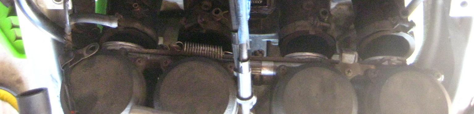
Now you are looking at your valve train and camshafts and sprockets and chain.

-Back to your pickup coil area. Use a 19mm socket and turn the motor CLOCKWISE (only!) until the 1/4 T marks line up with the upper 12:30 / 1pm O’clock position raised up built in ‘indicator’. I’m pointing at indicator below:


Look at cylinder #1 area (far left of bike sitting on it). The lobes should be facing away from eachother and up slightly close to 40 degrees / 45 degrees. If they face in, or cylinder #4 lobes are facing away from eachother, you have #4 cylinder at TDC. See here how #4 cylinder is at TDC.


Rotate the crank again at the pickup coil cover area a full 360 degrees which will put #1 at TDC.

The above green arrow is pointing to the #1 lobe facing out or away from eachother. (Arrow is not directional sign).
You can now measure your valve clearances. There are 16 to check. By setting #1 cylinder at TDC you can check all (4) valves of #1 cylinder, plus the exhaust valves on #2 cylinder, and the intake valves on #3.
Insert your feeler gauges between the camshaft lobe the the inverted shiny bucket below it. I am checking cylinder #3 intake valve while #1 is at TDC:

Feeler should have a slight drag on it but if you have to force one in, it’s the wrong size. Use the smaller number in that case. Write down each measured value for each specific valve. I made a rectangular chart with EX and IN tables and 8 boxes for each valve. Write down the numbers with something like that to keep track of each one. This is very important if you need to adjust your valve clearances. You must know all this information.
There are different spec values for the EX and IN valves. Clearance specs for our bike are this range:
Exhaust (EX): .22mm – .31mm
Intake (IN): .15mm – .24mm
Rotate the crank again at the pickup coil cover area a full 360 degrees which will put #4 at TDC. You can measure the clearances of all of #4 valves, the Intake valves on #2 and the exhaust valves of #3.
(You can also spin the crank again to the 2/3 T lines and check all 4 valves on one of the #2 or #3 cylinders if you like. It’s the same idea: as long as the cylinder’s Intake and Exhaust lobes face away from eachother and slightly up you have that cylinder at TDC and can measure the valve clearances for that cylinder).
If any of the valves are out of spec you will need to swap shims to alter the clearance to within spec.
If everything is within spec pat yourself on the back, you are done. Reassemble and go ride!
However, you probably will find valves out of spec if you waited awhile like me.
To remove the camshafts and to change shims and alter your clearances:
At this point, you actually want to have #1 cylinder at TDC. Recall if the indicator is at 1/4 T mark, either #1 or #4 could be at TDC right now.The manual glosses this over point, that either #1 or #4 could be at TDC just by lining up the 1/4 T mark.
Put #1 at TDC! If it isn’t (which way are lobes on #1 pointing – inward then #4 is at TDC), so turn the crank bolt at the pickup cover another full revolution back to 1/4 timing marks. This will now put cylinder #1 at TDC (#1 lobes are facing away from eachother right?).
The reason you want #1 at TDC instead of #4 is because the timing marks are much better and easier to understand and line up on the #1 TDC marks on the camshaft sprockets. Do not move the crank again once you’ve set it to #1 TDC and have started below procedures – Important!
Now look at your camshaft sprockets.
The rear one is the Intake marked IN, and the front one is the Exhaust camshaft marked EX.
You should see the IN — line at the rear of where the valve cover meets the head and the EX — line at the front of where the cover meets. They should be evenly horizontal. Below is the IN camshaft with factory line at the cover / case split:
Now count the links and / or rivets between those horizontal marks. My bike had the timing marks in between whole links. The book mentions links split the lines. Either way, use logic / math, the two lines should have 17 links between them and 34 rivets. If your marks are like the manual, you have 16 links and (2) half links between the marks which also equals 17 links (and 34 rivets).

NOW MARK your camshafts – both, and the sprocket with a line. THIS IS VERY IMPORTANT. I have written that in ALL CAPS, like I am almost shouting. It’s that important.
Skip this, forget this, and you have made more work for yourself and stress.  Make sure to mark them well. I used a metallic sharpie and that wasn’t the best as the marks nearly wore completely off from handling the chain. Paint pen / paint is best. Mark lines across both the chain and sprocket for timing alignment marks.
-Remove the CCT (Cam Chain Tensioner). It’s located under and in front of the carbs. I’m pointing to it.

-Remove the center bolt (12mm) first. This will release an under pressure spring and pin and copper washer with the bolt. Place aside.
-Remove the two outer bolts (10mm) now and remove the CCT housing from the engine. I had to whack mine with a rubber mallet, it was stuck in there pretty good. It popped out with some energy.
Now the camshafts have what’s called caps on top of them, big machined blocks of aluminum holding them down and inline (we could abbreviate them as Al Caps, haha).
 Look closely at the 16 bolts. They have little numbers beside them.
 Start to loosen the bolts a turn at a time in the order starting at #16 to unbolt (you tighten on reinstall starting with #1).
Do Not loosen the entire bolt. Just a little at a time to start until all the pressure has been released from the camshafts. If you don’t do it this way you won’t be able to get the caps off due to pressure misalignment.
You may want to remove the spark plug O rings here. At least be careful they don’t fall off and down into the motor:


Once the caps are off – again Do Not move the crank now again until the job is nearly finished!
When you remove the camshaft caps, be mindful there are 4 locating dowels in between the camshafts. They may have come out with the caps. Make sure where all 4 are, and that they are not missing or fallen down into the motor. They also have 4 very small O rings around them. I left mine in place as is (see pics). I ALSO left these lower spark plug O rings right where they were. This is where the manual insists to replace them. Anyway, I didn’t so there you go.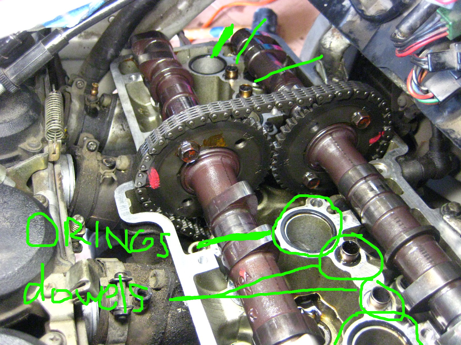
Next, You can in fact remove the camshafts without unbolting the sprockets like the manual says to do. You can move out the IN camshaft and sprocket together first and set aside.
 Have something right on hand to tie up the timing chain and keep tension on it so it does NOT come out of the teeth of the crank down below in the motor. Remove the EX camshaft and tie up the chain not letting the chain fall / drop / slacken much at all.

I used the throttle cables to tie the chain to.

With your camshafts out you have now exposed your buckets, the shiny metal round things upside down on top of your valve.


You need to remove the bucket and shim for any valve that was outside the factory spec value. You can leave in ones that are within spec. I had 14 or maybe 15 out of spec so I just pulled them all.
 The shim is stuck under the bucket in the above pic. Those shims are small! Like a small watch battery size.
I used a very strong magnet to remove them easily. With a strong magnet the shim should also come out at the same time under the bucket. Place the magnet center of the bucket for removal of bucket and shim together.
Take them out one at a time and put them in specific labeled spot for each valve. Each shim is different thickness if the valves have ever been serviced and it’s imperative to know which came from which for measuring. I used an egg carton and half dozen egg carton and marked one side IN and one side EX and put the buckets and shims in there to know which was which. 
So now you need to measure each shim that came out for any valve clearance you need to adjust and write down the precise thickness of them for each specific valve to tour table. Record final values in mm / metric as the charts are in metric as are the shim numbers for ordering.
So there are going to be a few figures for any valve clearance you want to adjust:
– Measured clearance
– Measured shim thickness
– Desired clearance
As the clearance are a range of values, you just need to get in that area. I opted for trying to make the valves all on the looser side of the spectrum as they will tighten with miles.
Then you can consult the Kawi manual lookup chart to find out what size shim you need to replace them with.

Write numbers down on paper, etc… I used a little whiteboard. The shims that are calculated to go back in are sitting on the board.
You can mix and match and replace with existing / used shims. You likely will find at this point you may have to go get certain specific shims that you need.
Basically the way this all works is, that generally the valves tighten up with mileage and the clearances lower / tighten. To get a larger clearance you need to get at thinner shim.
So if a shim that came out was measured at 3.00mm and your clearance was say around .20mm too tight for the spec you want, you would in this case replace it with a 2.80mm shim.
How about a specific example from my bike?:
On Cylinder #1 I measured my left exhaust valve at .038mm (way too tight!)
Spec for the exhaust is range of .22mm – .31mm
The shim that came out was a 2.95mm
Chart lookup value calls for a 2.70mm shim
New clearance once installed measured a .279! Perfect, the high side of the clearance range.
If you check some math there, the difference between the old and new shim 2.95mm and 2.70mm is .25mm
.25mm added to original measured clearance of .038 = .288 very close to the figure I got above. This is how it works. (in my case the .038mm feeler gauge could barely fit in between the lobe and bucket but it was the thinnest one my set came with).
You can calculate it yourself or use the chart. I used the chart to start, and then re-did all the math myself several times to make sure I was getting what I needed. I did not want to do this twice.
Once you have it all figured out (my first time – I took hours writing and calculating I think), get your new shims and install them in the proper valve spot. Then re-install your buckets. I kept my buckets stored and back in with the exact valve it came from.
Once they are all in it’s time for reassembly.
-Make sure your crank is still at 1/4 T mark.
Lubricate the bearing spots that hold the camshafts with motor oil. Or make sure they are still oily from before at least.
-Place your EX camshaft in first and line it perfectly back up with the link on the chain your mark meets up with on your sprocket. It will make this a fairly taut fit against the chain (and the crank below). That’s good.
-Install the IN camshaft next.
OK so here’s where you can toss some manual sh*t out the window. It states to have the camshafts in perfectly and flat down so that the IN — and EX — line marks are perfectly lined up with the case line and no slack on the chain. Yeah, good luck with all that. You’d need a circus strongman and or about 6 hands to shove the camshafts down on top of some resisting valve springs and hold it all perfect… plus it’s a waste of effort and time.
Think about it, the only thing that moves those sprockets is the chain which is only moved by the crank below. Even if there is some slack or not perfect lining up of the IN — mark and EX — mark on the case line, it will align itself.
JUST MAKE SURE your sprocket and chain link marks are perfectly lined up on both. You made those marks right? And that you never let pressure off your chain – and therefore let it slip off the crank sprocket deep down below.
Have the front EX camshaft tight-ish is nice (doesn’t have to be) and let the IN camshaft go where it’s going to go – it won’t be perfect. There will be chain slack between them. That’s ok, it’s all gonna fix itself.

If you removed any of the 4 locating dowel reinstall them and make sure the small O rings are around them. Also if you are replacing or removed the lower spark plug O rings, put them all back in now.
Now re-install the camshaft caps starting with #1 bolt. I tightened each one until there was resistance and then went slowly a little at a time in order #1 – #16. This will flatten down the camshafts. But don’t worry they are off yet. DO worry and make sure the chain doesn’t jump off either sprocket’s teeth.
By tightening down the caps, they will likely rotate and move around your camshafts a bit like how it happened to me below. This is ok, just Make Sure your marks are still lined up, and that there is the 17 links between the horizontal marks on the sprockets. 

-Once the caps are tightened to 12 NM (104 inch/lbs) of torque, YOU MUST reset your CCT. If you put it back in as it was you will likely break something and cause damage. Reset it.
You do that by pressing in the little button and then pushing back the little “plunger” (foot thingee) back into it’s holder. I’m pointing to the ‘button’ you depress to push the plunger back into the housing.
This pics shows the ‘plunger’ retracted after resetting it:

-Now re-install the CCT housing, the raised arrow on it aligns horizontally at the top (but not pointing ‘up’).
-Bolt in those two 10mm bolts on the housing.
-Reinstall the bolt, copper washer, pin, and spring into the CCT housing. It will be tad difficult as the spring will push back on you, but get the bolt in and tighten to 9.7 NM.
This will now engage the CCT to put pressure on the chain.
Make sure your painted on marks are all lined up and you have that 34 rivets / 17 links between the sprockets IN and EX lines.
-Now go turn the crank clockwise: Most likely you will see the slack between the sprockets go away instantly!
The chain will pull both camshafts where they need to be. Before turning crank:
After turning crank:
-Rotate the engine many revolutions to set the shims and make sure everything feels normal and sounds good. If you messed up the timing now is, well, the time to figure that out. Any major resistance stop! You may be mis timed and forcing valves into pistons.
-Now you will re-measure your valve clearances and make sure they are all within spec. If they are not – you know what you’re doing next. Figure out which ones are off, figure out the proper shim, and get it / swap it in from spares once you’ve taken the caps off again and the camshafts out. Hopefully you’ve gotten it all right and won’t have to do this (I did not have to).
If you have gotten them right – congratulations! You owe yourself a beer tonight.
So time to re-install it all.
What I did was turn the motor several times by hand to make sure it all felt right and then re-installed the pickup coil cover. I cut my own gasket for it as the old one was toast on removal.
-Then reinstall your valve cover and gasket. Make sure to use sealant on the (4) lower half moon cutout parts of the gasket – I used hi temp RTV silicone sealant. I got my cover wiggled back in less than one song on the radio – it was finesse-y but not too bad. I moved the wiring loom up a lot and slid it back in under the left side first.
-Reinstall the valve cover bolts and torque to 9.8 MM (87 inch/lbs).
-Re bolt in the black plastic heat shield
-Install the spark plugs.
-Install the coils and mounts back and the spark plug boots.
-Re connect the ignition coil wiring.
-Re install your carbs into the boots and tighten the band clamps.
-Reattach your choke cable to the carbs.
-Re-attach the negative terminal of the battery.
Now at this point I decided to test fire the bike. I had fuel still in the fuel lines and carbs so I fired it up with the tank off. It cranked a little as I had the choke in wrong position but fired right up and sounded great!
Then reassemble the rest of the bike.
-Reinstall ram air tubes.
-Reinstall airbox and then all vacuum lines and hoses.
-Reinstall the fuel tank and fairings.
Congratulations! Go ride!
This was my first I4 motorcycle valve adjustment. (I’ve done my 16 valve car before and an 6 valve inline twin Honda motorcycle – that was cake). It’s not a really difficult job, I just got agitated when I could not get any feeler gauge to go into the exhaust valves on cylinder #1 and #4 (because they had tightened to zero clearance and I did not know that yet) and a few things in the manual were not clear and an item wrong.
A weekend timeframe would be a good time estimate if this is your first time and you are somewhat handy in the garage. You likely have to factor in getting certain shims. You might be able to get this done in a day. But you will feel really good about getting it done and probably take half the time next time.
My motor sounds better, starts way better than it ever has since I’ve owned it, I have better low end power. I had 3 exhaust valves at zero, or less than .038mm anyway, clearance. I was risking burning a valve and probably had lower compression and power as a result. I was pretty thrilled to get this done.
Posted in DIY, repair and tagged adjust valves, clearances, DIY, DOHC, how to, i4, inline four, Kawasaki, Ninja, Valve adjustment, valve clearances, Zx6e, zzr600 by green
Debaffle stock exhaust Kawasaki Ninja ZX6e. Exhaust Mod. How to. DIY
This is a modification to the stock dual can muffler exhaust on the Ninja ZX6E 1993 – 2004 also known as the ZZR00 in 2004 and in Europe.
This was all inspired by “mechanicalmadness” member of the old zx6e.com forum. He did this exhaust mod and made a great write up although it’s gone from the internet now.
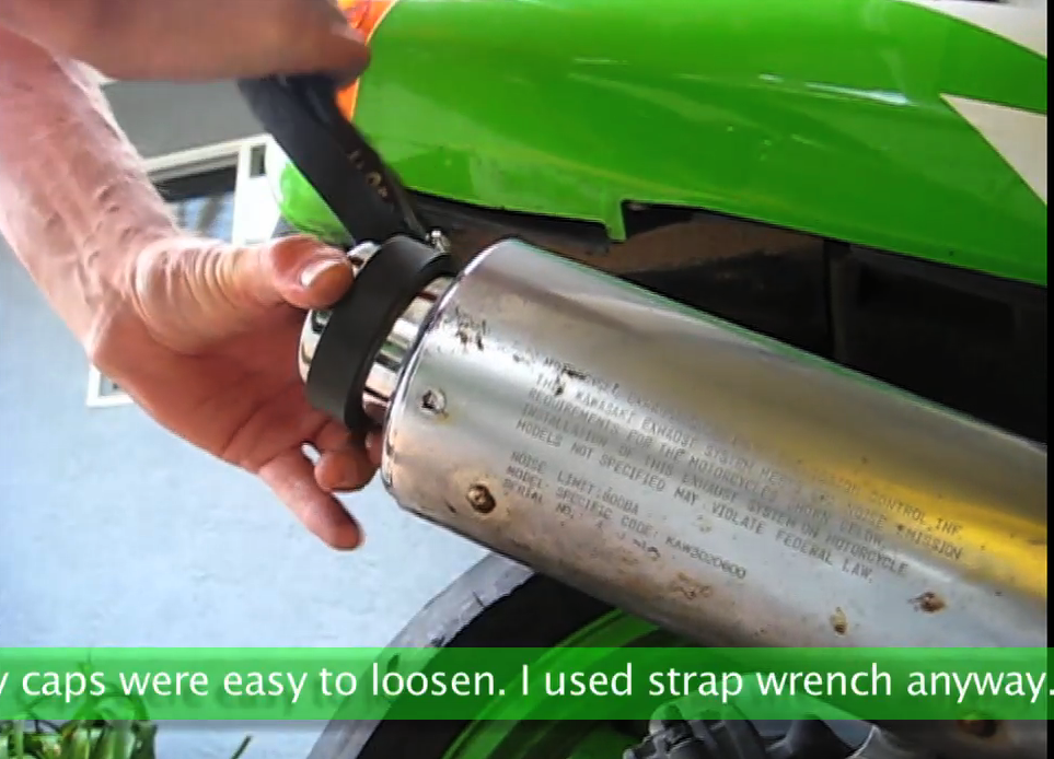
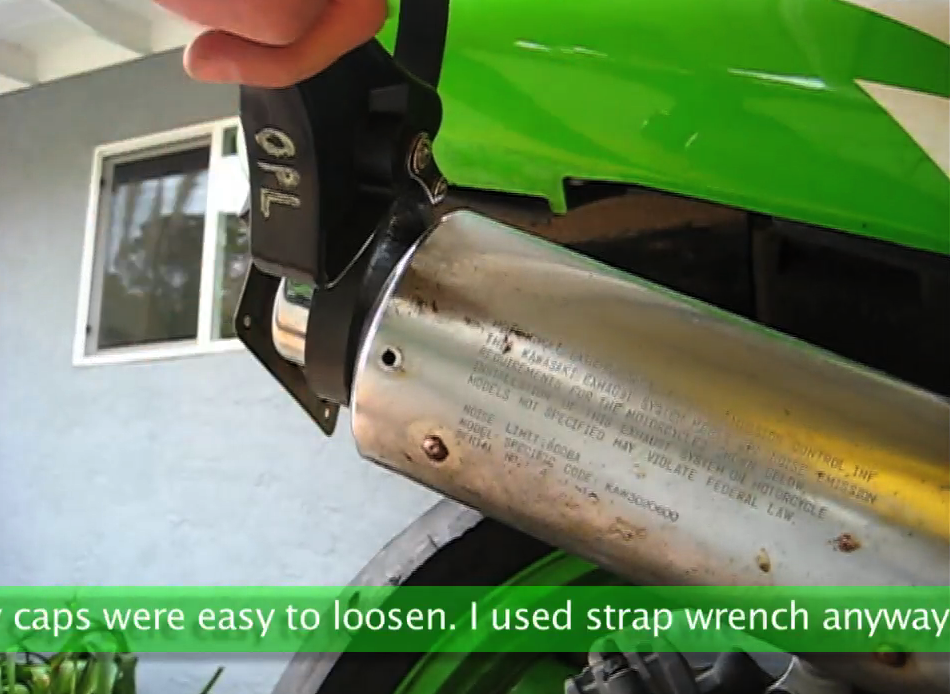
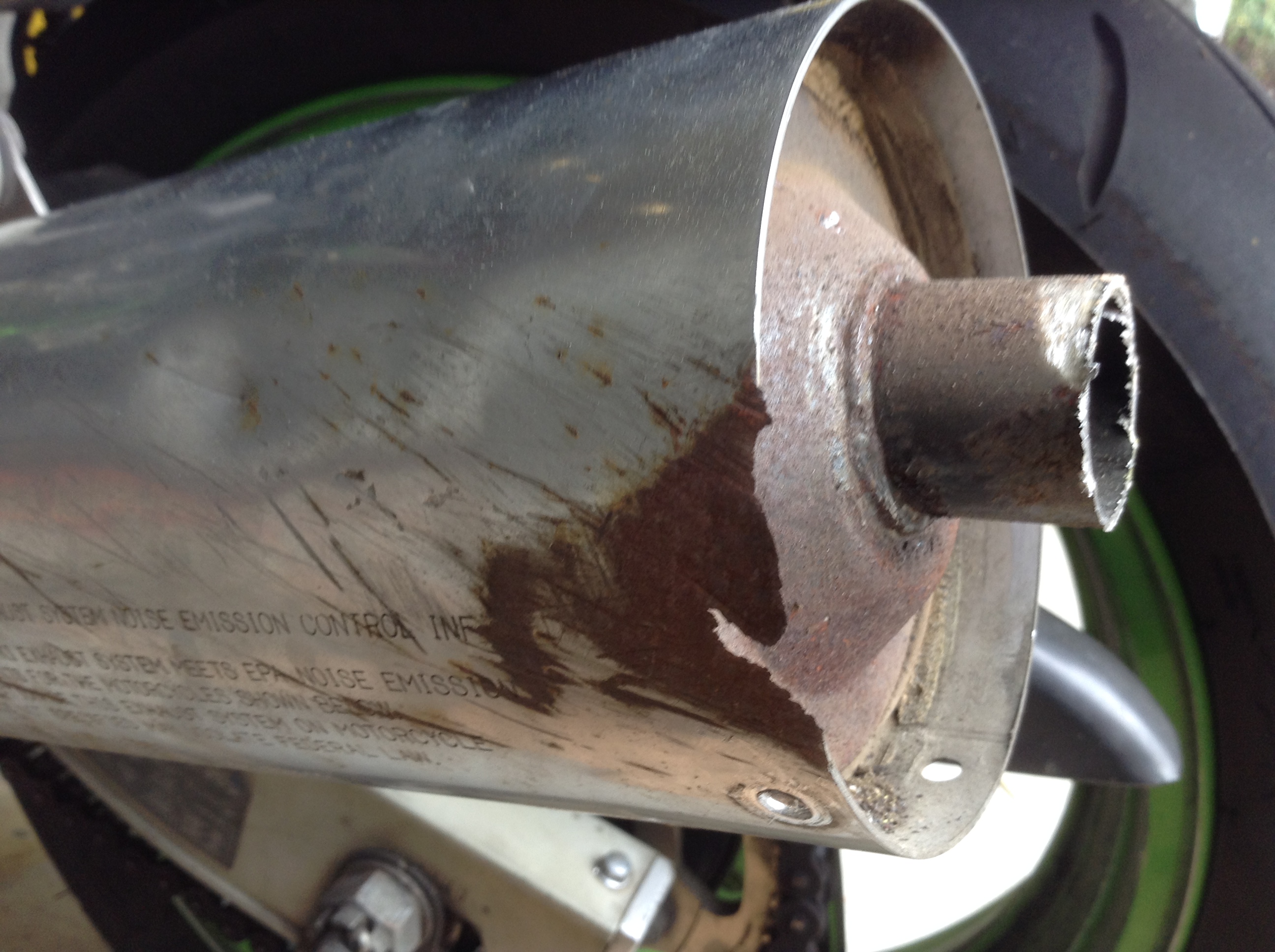
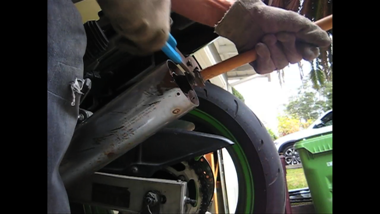
First thing, you have to drill out the exhaust cap rivets, there are three per side.
Next, you need to spin the exhaust caps out. I used a strap wrench. There is some sealant in there that does not let the cap release easily. Mine were easy to loosen though, perhaps due to their age.
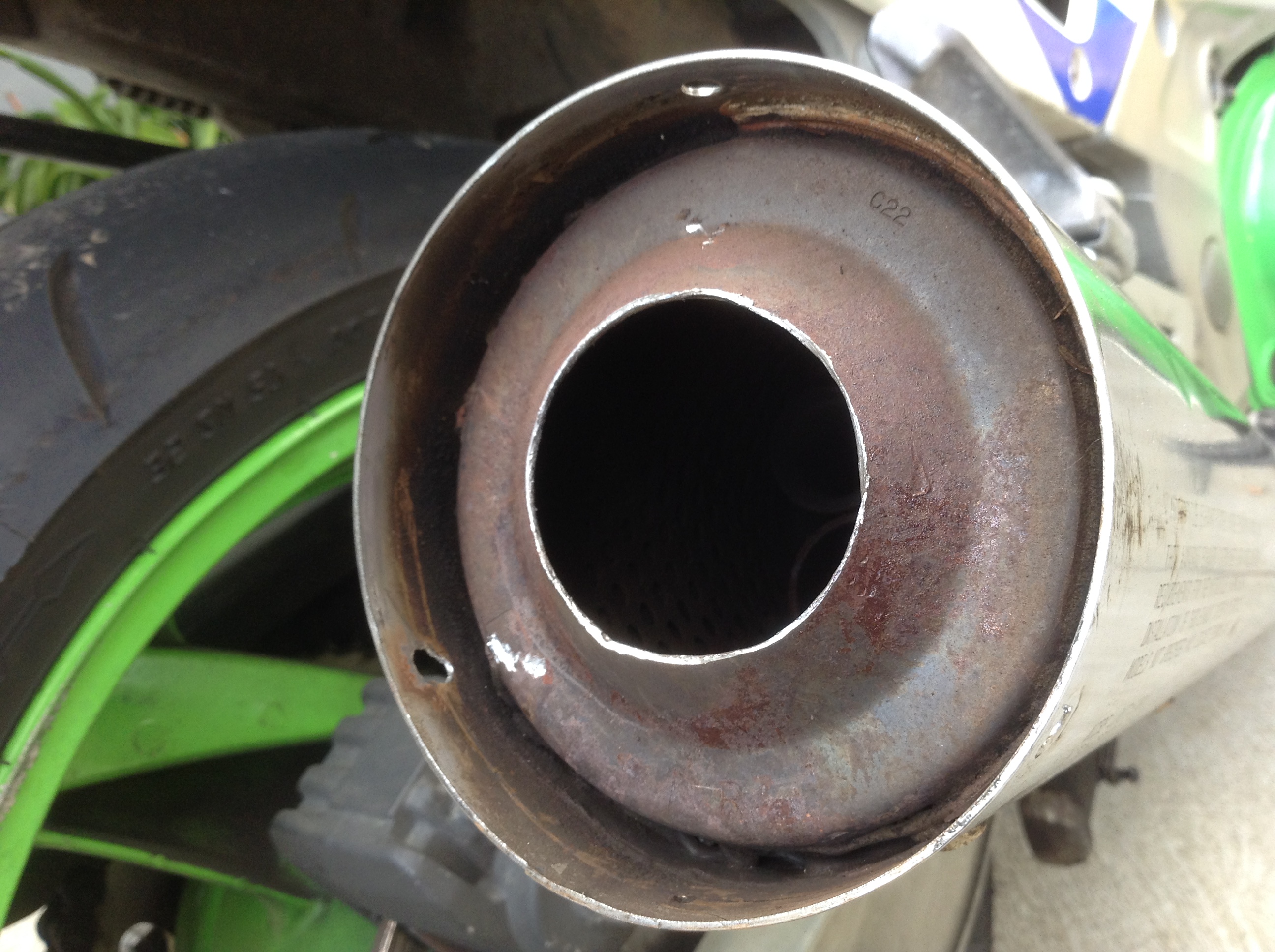
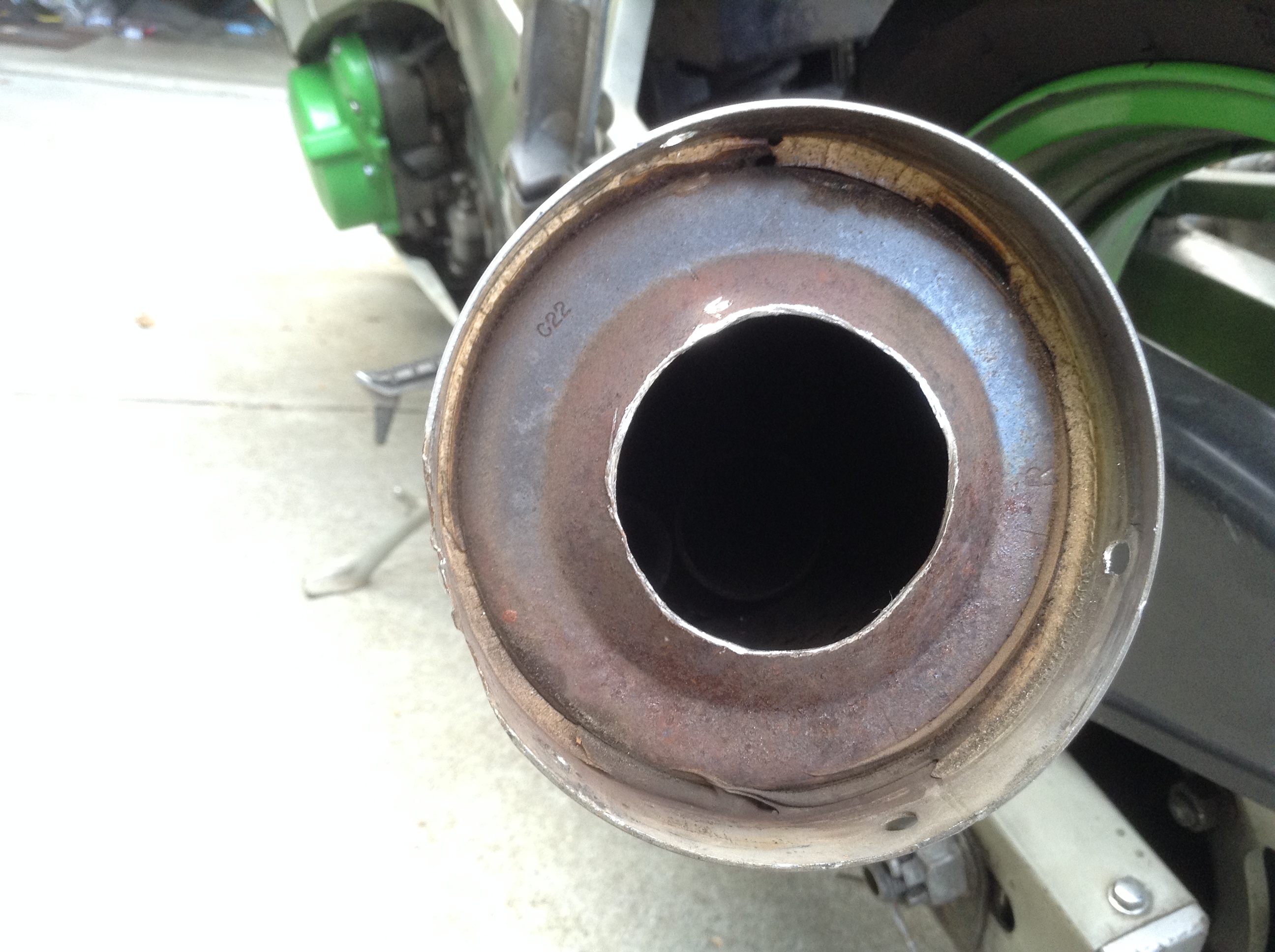
Removing the end caps reveals this:
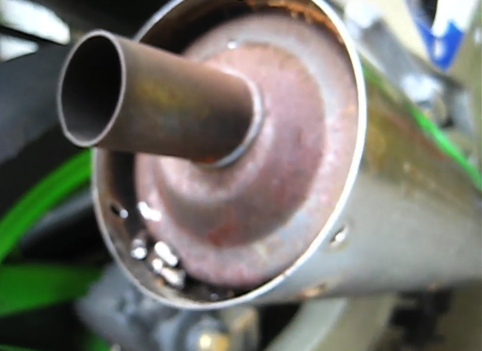
This is the final tail pipe that comes from 1 of 4 pipes inside as you are about to see.
Then, I used a 1 + 3/4″ (44mm) hole saw for metal to make it fairly easy.
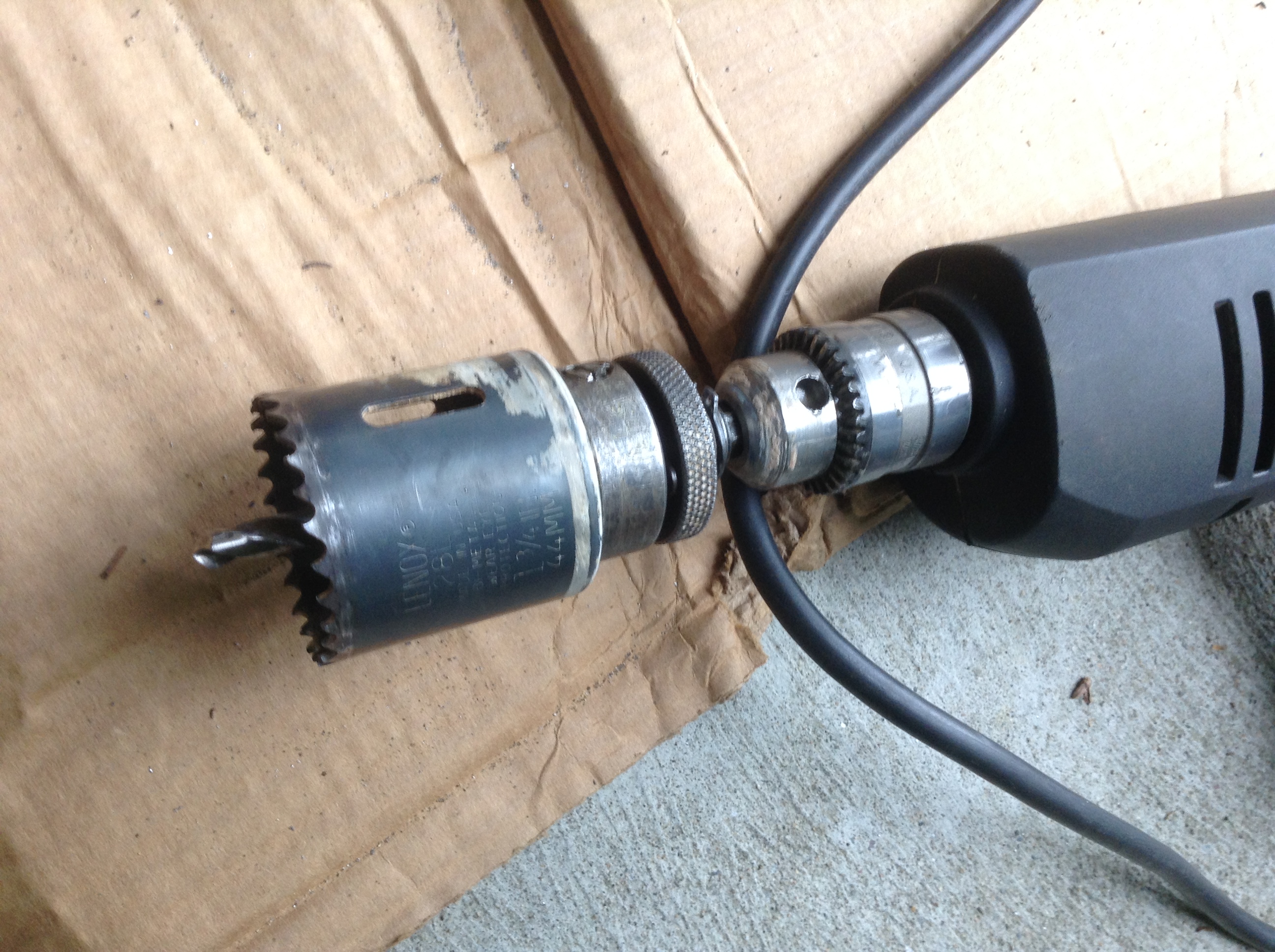
To get the holesaw to bite into the base of the end of the exhaust I cut the tail pipe off with a hacksaw first – maybe 1.5″ off or so.
Then the hole saw will easily reach the metal to cut.
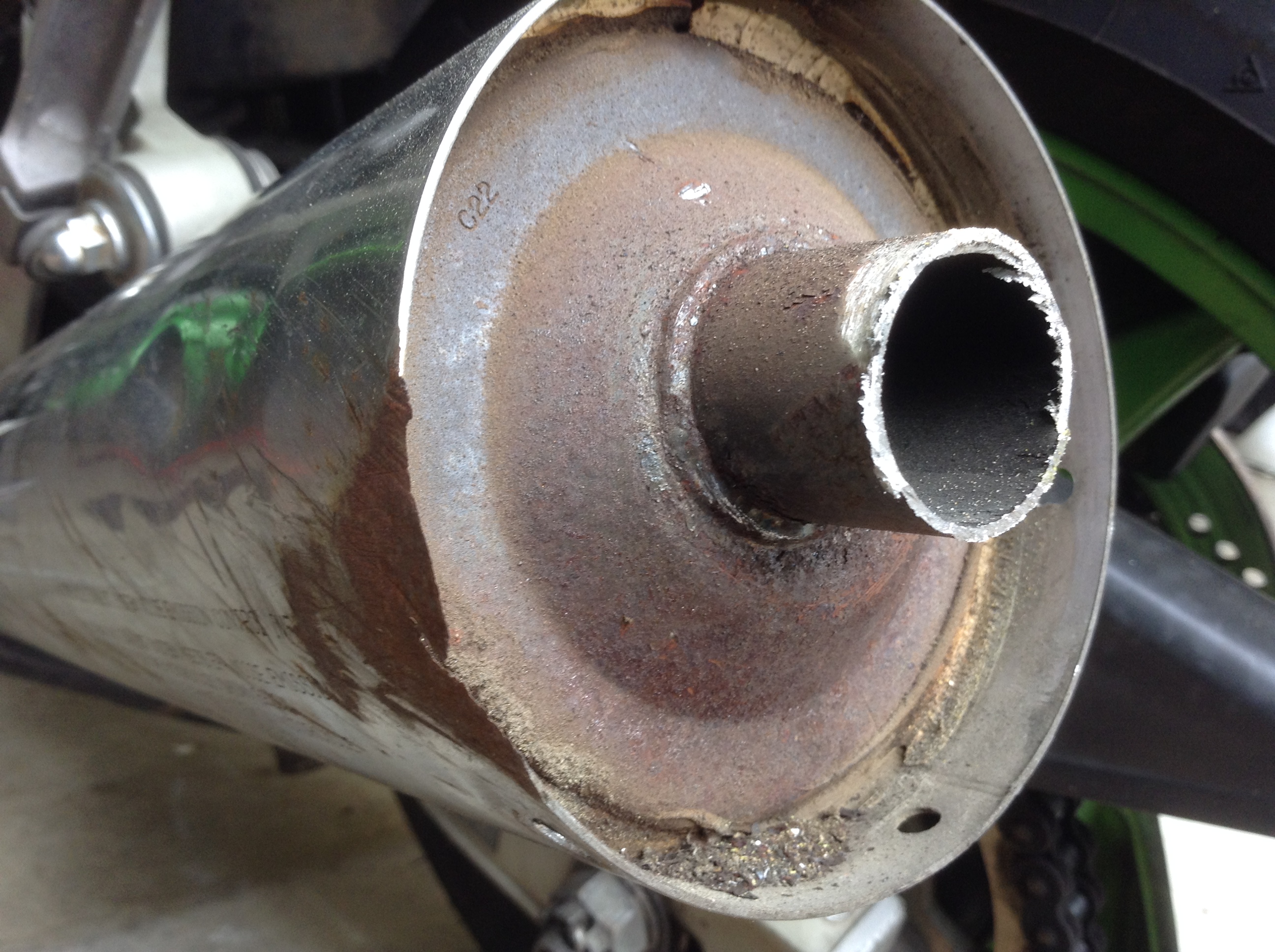
Once that’s done, you now need to break the inside weld spots on this tailpipe / baffle. I jammed a wooden dowel in there, and used lockjaw pliers to put a lot of force on it, mostly rotating. You might find this step easier with a larger hole saw hole, but I didn’t want to go too big here.
It took some time but eventually you fatigue the metal and snap it off and out of there.
You can now see the insides of the muffler. You are looking at the plate of the middle chamber.
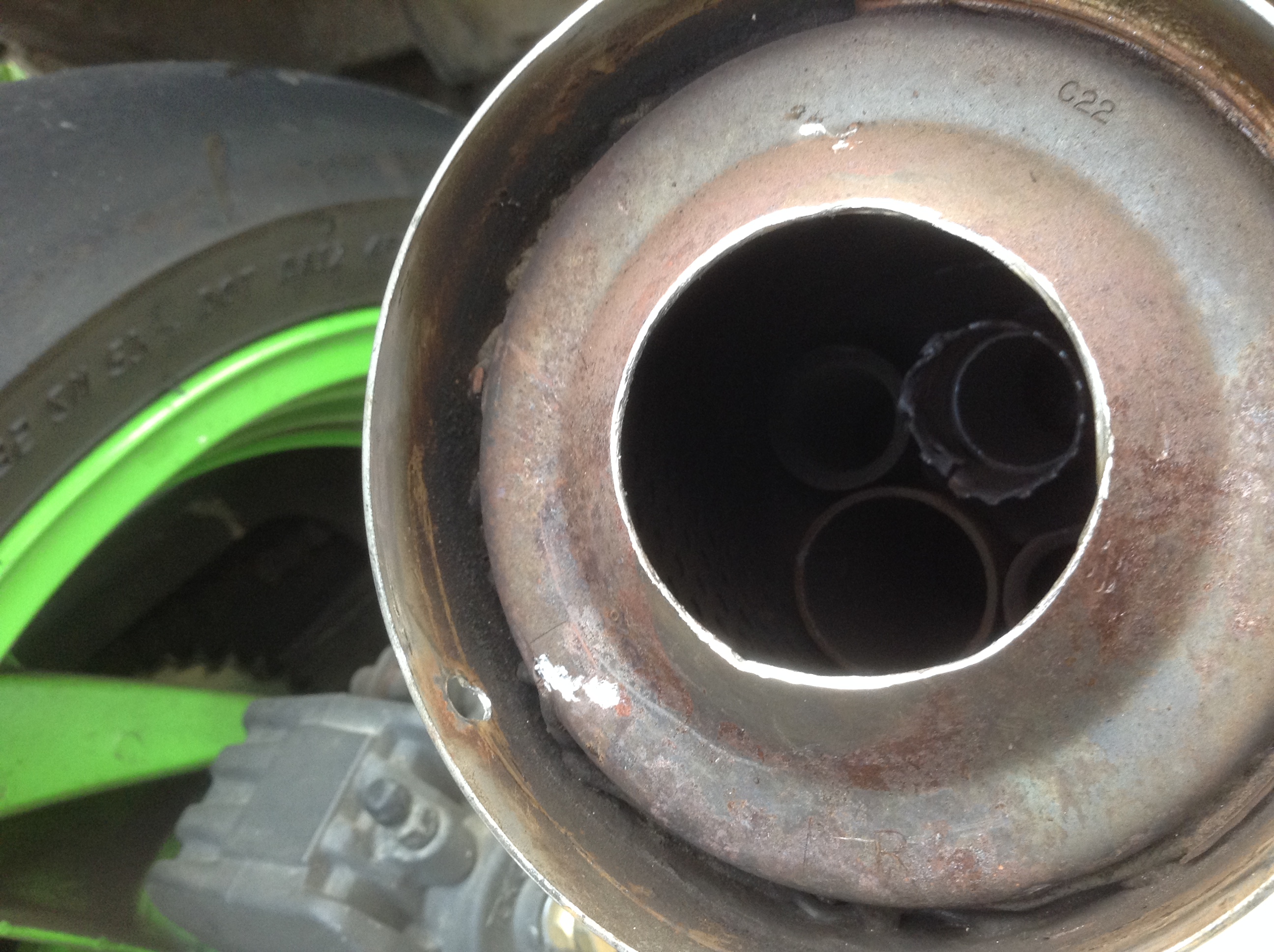

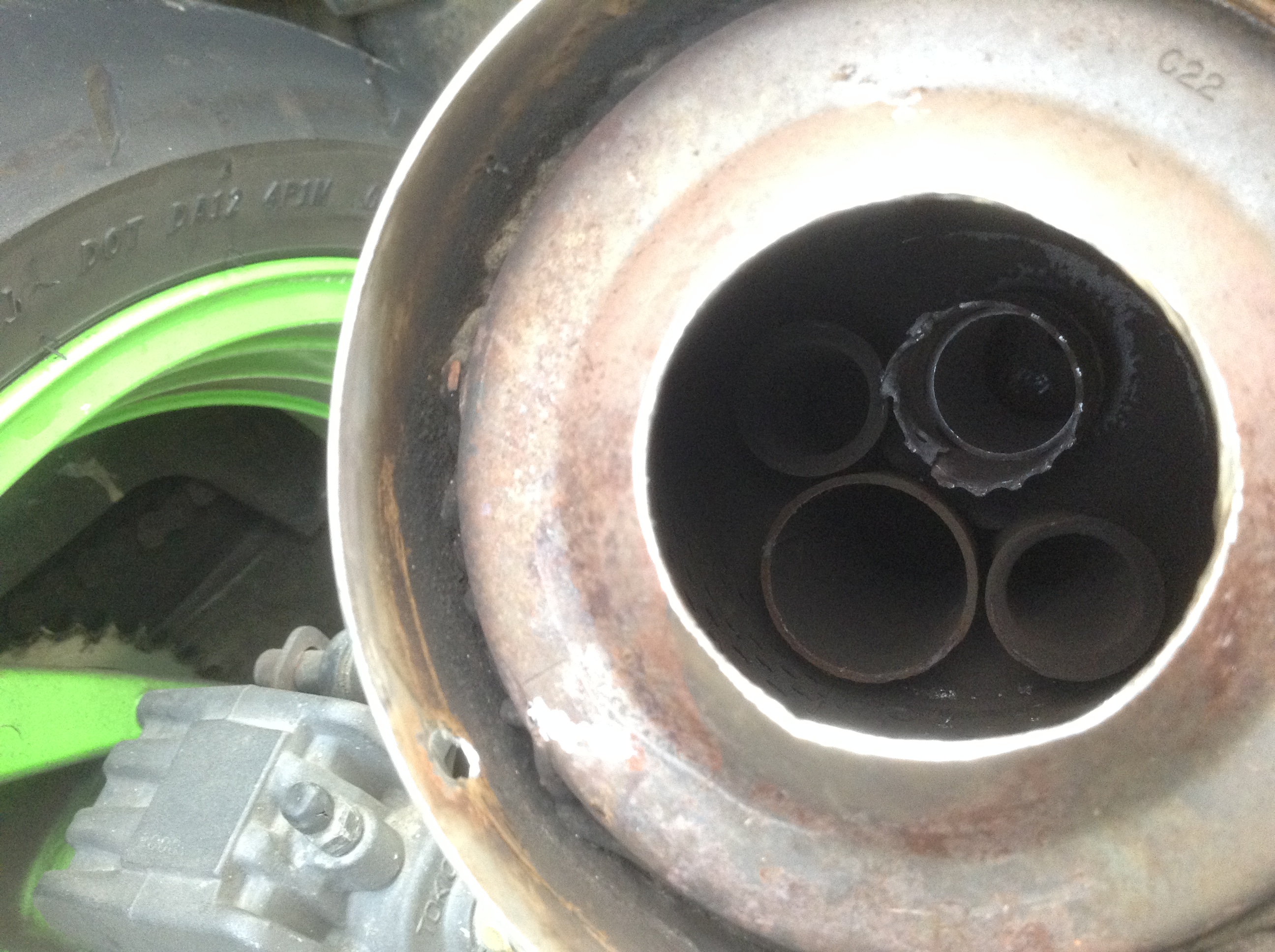
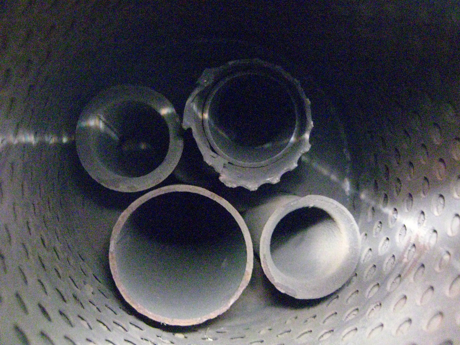
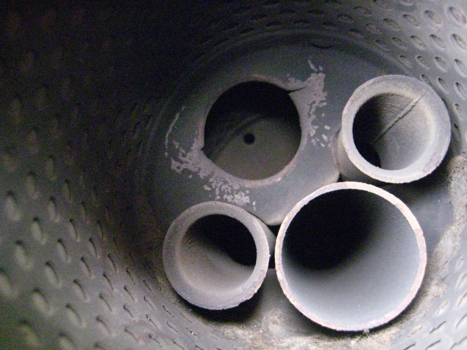
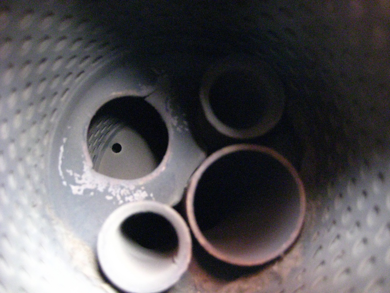
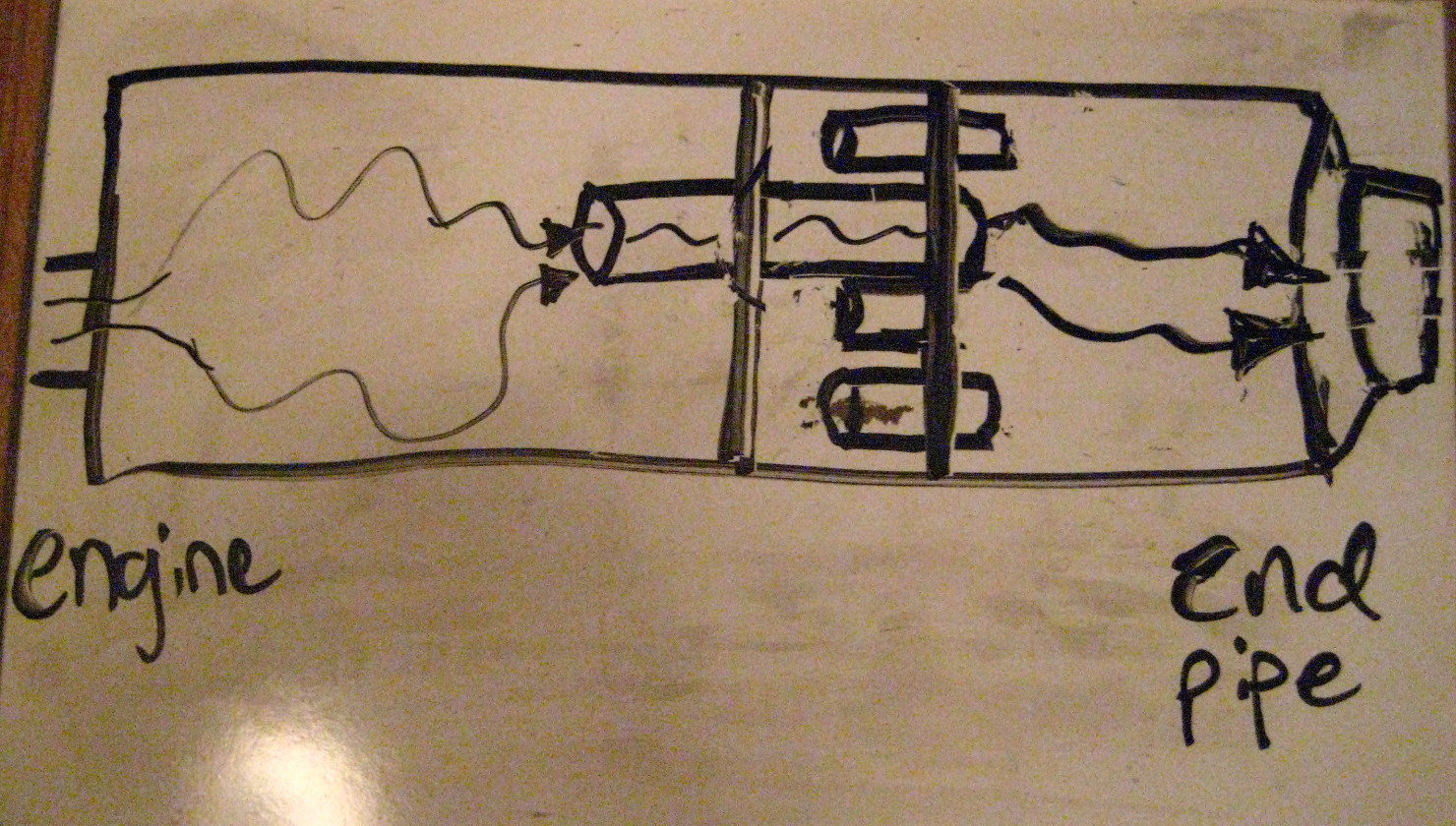
These exhausts have 3 separated chambers. What this mod does is effectively eliminate the middle chamber AND cuts out a large back and forth pattern the exhaust gases used to have to follow backwards into the middle chamber and then out that small final tail pipe / baffle. With it gone, the gases enter the first chamber and then exit out the larger diameter pipe, bypass the middle chamber altogether now, and then exit into the rear chamber and have free outflow out the back now.
Before:
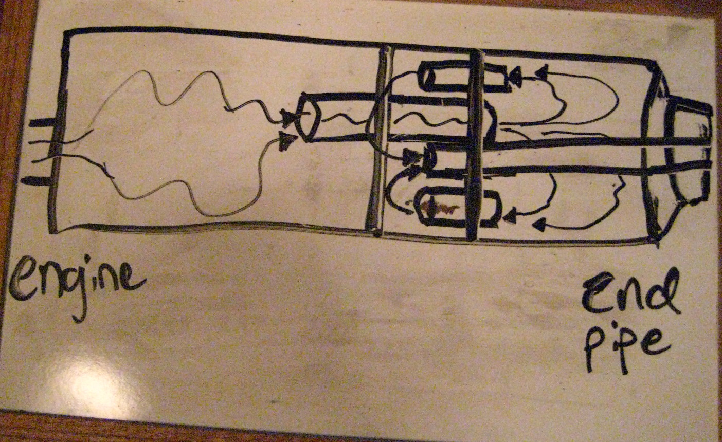
After:
Here is a photo of an ‘exploded’ stock muffler:
Yo
Result?:
It sounds SO much better than stock. Idle is amazing with a nice throaty burble. Cutting this all out rather than drill holes around the end tail pipe makes it deeper / bass-y sounding, and not raspy at all.
Depending on load and throttle position etc… it can get a little loud and drone starting as early as 3500 and through 5000 rpms. Again, depends on several factors. By 6000 + the exhaust sounds sweet and great!
My bike idle smoother at lower rpms with this as well. It burbles nicely, it really sounds fantastic.
This little mod has totally changed the feel of the bike. It was such a quiet bland exhaust before. Some people have done this and found it too loud for them.
I have worn earplugs riding for the past 2-3 years to protect against hearing loss (from wind noise), and I LOVE this exhaust with my ear plugs in. I am also noticed more by cars driving around as they have more of an audio warning I am nearby.
I will posting a proper comparison of the before and after video with same video gear with the same manual settings so you can hear the difference.
It’s a free exhaust tone modification and I did it in just a few hours on the weekend. Enjoy!
Posted in DIY, repair and tagged baffle, chop, debaffle, debaffle cans, debaffled, exhaust, exhaust mod, Kawasaki, muffler, Ninja, stock exhaust, Zx6e by green
Fuel hose Fuel Line size diameter 8mm I.D. 13mm O.D.
I’ve spent a lot of time searching for this info and finally figured it out. It’s hardly disclosed really anywhere.
ZX6E / ZZR600 use 8mm I.D. (Internal Diameter) fuel line / hose, with a 13mm O.D. (Outside D.)
In a pinch you could substitute 5/16″ hose as that seems to be much more common. You don’t need the common really thick auto parts version as that is used for higher pressure F.I. motors and we don’t need the thicker reinforced walls for carb low pressure fuel. Worm
One suggestion, Parts Unlimited makes a clear blue tinted fuel hose that is 5/16″ and they say long lasting and chemical / fuel resistant and fairly kink free (I think it’s polyurethane based). I got sold some 1/4″ Parts U. from the local Kawasaki dealer for my bike (wrong stuff – too small), and I have crammed it on, but it’s a p.i.t.a. to stretch onto nozzles, and then your old fuel line clamps won’t work as the O.D. is too small. It is pretty flexible stuff, stronger than stock it seems and it’s nice that you can visually see fuel in the system and moving for diagnosing / reassurance. It would be good for pump to carbs, fuel filter to pump, and probably pump to fuel tap / petcock runs. The short main and reserve to petcock / fuel tap runs have some pretty tight turns in them. So far I have left them and might order stock lines there.
BMW E28 era cars also use the same hose. You could get some 8mm from a BMW dealer.
Posted in DIY, repair and tagged aftermarket, diameter, Fuel hose, Fuel line, Kawasaki, kind, Ninja, replacement, size, sizing., type, Zx6e, zzr, zzr600 by green
Magical Monterey trip. Big Sur. Great work!
Had an amazing work trip down to Monterey. Working at the Concours d’Elegance, something I have always wanted to see.
Now there were far more Lambos down there than Prius cars!
Client put me in a magical hotel, the best hotel experience I’ve ever had. Monterey Bay Inn. The staff was terrific, and it was such a small boutique hotel on the water there were no common space rooms, so that meant breakfast was brought to your door every morning!
I was surrounded on two sides by beautiful Monterey Bay on the top floor of the Inn. I found out later I got The Honeymoon Suite – literally – my work buddy had been there last year for a wedding. I had a marble bathroom and open tub that looked right out to the ocean and a balcony over the water. It was fantastic every morning and often I’d get back to enjoy it in the late afternoon.
The cars were awesome there. And I got released early one day (we started early most days), and I got changed fast and took Green Magic down the famous Route 1 coastline into the heart of Big Sur.
At the final place I stopped at – just beyond Julia Phiefer beach with the rock formation cutout – I pulled in a great turnout with beautiful southern view. There I saw whales galore! Breaching out of the water, I couldn’t count the numbers I saw. I only had my pocket Canon SD camera with me with silly zoom so here’s the best pics I could muster with it.
We had great meals for the trip, frequenting the Tiki Bar restaurant maybe 3 nights. An easy walk for our crew from two hotels.
I’m hoping to go back next year for this event, it was the best assignment I’ve had this year!

My beautiful hotel room views out both directions:


Riding down Route 1 to Big Sur Saturday.


 The magical view from Nepenthe restaurant.


 Julia Pheiffer beach, near where I turned around.


 Those are the flukes of the whale’s tail. Also the back of one coming out of the water highest mark above the rocks.


The Bixby Bridge.

 Riding down to Monterey on day one. Wednesday. Zipped out of work in Belmont asafp, to beat some traffic and make a crew dinner in Monterey. Got there a little early so snapped some pics just north of town. Had to pack a fair bit of gear for 4.5 days and a shirt and tie and fancy shoes for Sunday.


 My favorite car of all time: 1966 Ford GT40. I would own one if I could! Sex on wheels.


 Hotel and balcony and a breakfast morning. The early breakfast moments each morning right by the water were sublime.
 Grill of the 1937 Delahaye 145 Franay Cabriolet.

Last full day work there: Sunday show. Yes, that’s an actual ’65 Shelby Cobra Daytona.
Posted in Touring and tagged Concours, Concourse d'elegance, Ford GT40, Highway 1, Kawasaki, Monterrey, Ninja, Pebble Beach, sexiest car of all time, Zx6e, zzr600 by green
How to replace Clutch on your ZX6E Ninja. Easy, step by step how to DIY
In my opinion, this is a very easy job and not much harder than changing oil or spark plugs.
Easier Tips: An easier way to is drain your oil. You can gangster lean the bike a lot towards the kickstand side of bike. I’ve read pushing bike onto 2x4s and using sidestand should make it not leak much when you pull the clutch cover, but I was near my oil change interval anyway, and figured I’d rather have more secure stable bike to work on, on the centerstand.
I also pulled my clutch lever in, then held the lower clutch lever down below on right side in place with a short 2×4, and disconnected the cable at the handlebar. I then rotated the lower clutch release rod, it’s attached to the hinged lever down on the lower right bottom of the clutch housing where the clutch cable hooks into. The rod is inserted up inside the clutch housing. Rotate the rod gently to free it, and then slide the rod out the bottom of the housing.

1) Drain oil (or not – see above)
2) Unbolt the clutch cover.
It’s the lower right large cover on side of bike, where your fill up your oil. There are about ten 8mm sized bolts you need to remove here. With the old gasket installed, it may be a little stuck on there, I gently, and I mean gently, gave it some taps with a 2×4 scrap to help free it.
3) Remove the cover.
Voila! you’re looking at your clutch assembly. Yes, it’s this easy.

4) Remove the five allen bolts that hold the clutch springs in.
They are long bolts and unscrew slowly, so don’t worry the springs aren’t going to shoot out at you or anything. You now will see your clutch metal plates and friction plates all stacked in on the clutch basket.

5) Remove metal plates and friction plates.
Just pull them out with your hands. Keep track of the order of them as you remove them and stack them. Basically, they alternate a friction plate, a metal plate. 7 friction plates in total. These are what you will want to replace with your new clutch kit (along with springs most likely). My inner most one was worn to 2mm, way too worn. They need to be at least 3mm, and a mm here or there spread out over so many plates adds up! (That’s what caused my clutch release rod to slip out, not enough thickness overall to the clutch plates due to wear. And picky shifting needed with the clutch this worn. I had lengthened my clutch cable {loosened} it to the maximum length and had nothing left.)
Look at your metal plates too. If you cannot see the little ‘dimples’ in the plates, they are almost certainly too worn down. 
 The divots just give the oil a place to hang out, and help keep the plates lubricated and freer. Check for excessive wear, and warpage. Easy way is place the metal plates flat on a piece of glass and try to slide some thin gauge feelers under them at numerous spots. Anything over .05mmm means they are warped. You should consider replacing warped or very worn metal plates. Otherwise, most people sandpaper the surfaces a little to scuff them up and reuse them.
Here, I scuffed the metal plates up with Emery cloth ‘fine’ sand paper:

6) Soak your new clutch friction plates in your motor oil for at least 30 minutes if not longer before installing, this helps avoid excessive wear on the dry plates on the first startup.
7) Remove all the old gasket material on the cover and the motor side.(I carefully used a razor blade).
8) Reinstall your new friction plates and metal plates alternating. The final outside plate does NOT go in the same deep slot grove in the clutch basket like the others do, rather it gets rotated slightly and fits in it’s own separate tab.  You can see that outer shallow tab opening in the above clutch housing photo above. See where the red line is pointing to at the top (not where the white text bubble has a small pointer). This is important to get this correct to avoid clutch slippage later.
Replace your new springs unless you decide to use your old ones.
9) Fit your new gasket (or something like Permatex gasket maker), and mount the cover and rebolt it in. I make my own from FelPro gasket paper.
Here are my new friction plates installed. Notice the outside friction plate is aligned in separate cutout tab in the clutch basket.


New springs and cover installed:

Reinstall your clutch cover and tighten according to the torque specs, which are 8.8 Nm or 78 in-lbs. They are not super tight. Push back in your clutch rod if you removed it, make sure to gently insert it and rotate it so it catches on the clutch release pin under the cover. Also, hook back up your clutch cable if you released it.
If you drained oil, add new oil. Make sure to not sure regular 10W40 auto oil, it has friction modifiers which can make the clutch slip.
Now make sure to adjust your clutch cable as it will be different from a worn out clutch. Adjust at both the handlebar and by the clutch housing the cable adjusters.
You can find special motorcycle Valvoline 1040 wet clutch safe oil, for example. I’ve used that the past two oil changes but I decided to switch to pure synthetic oil this time around doing my clutch to Shell Rotella T6 5w40 diesel oil. I’ll post on this blog how I like it, I’m hoping to have cleaner, smoother shifts!
UPDATE: I love the new clutch and I’ve ridden several thousand miles on it with the new Rotella T6 synthetic oil. I have much much smoother shifts with the new clutch.
Posted in DIY, repair and tagged clutch, clutch plates, DIY, friction plates, how to, Kawasaki, Replace, replacement, yourself, Zx6e, zzr600 by green
DIY waterpump rebuild (proper thread). Published from old zzr-international.co.uk site by dirtdoggle
DIY waterpump rebuild (proper thread)
Postby dirtdoogle » Tue Aug 21, 2012 11:43 am
I apologise in advance for my poor pics, nerve damage in my right wrist makes me shake a wee bit 😉
What you need:
A ZZR4/600/K/D, haven’t done one on the N/E but I think they’re the same
10 and 8mm spanners
Many hammers
Cigarettes
Socket set
Assortment of decent screw drivers
Circlip pliers
Extensive knowledge of grunting and swearing
Bearing puller really, really helps
Parts: Loctite sealant or similar
A wee bit of grease (if pedantic like myself)
Bearings: Two 12x28x8 stainless steel and must be 2RS sealed type (these cost me a grand total of $5NZ)
12 x 28 x 7mm radius oil seal
12mm external circlip
Rear water pump o-ring http://www.ronayers.com/ProductDetails/ … KU/1088282
Front water pump housing seal http://www.ronayers.com/ProductDetails/ … KU/1088281
Righto what you want to do:
Remove your bottom fairing (no pics, my bike obviously hasn’t got one, fairings are silly)
Drain the coolant, if unsure of how to do this, step away from the bike and go have a coffee.
Remove both hoses to the water pump
Un do the top and bottom 10mm bolts on the front of the pump
Ease the pump out
Now the fun begins.
Remove the remaining bolts from the pump cover and open ‘er up
Should look like this, hopefully…
Image
Now flip it over so you’re looking at the back
In theory, you’ll be looking at an oil seal
Image
Pop this wee fellow out and you’ll be able to see a circlip on the shaft holding the bearing in
Whip that out with the previously mentioned circlip pliers (or get real handy with a flat blade screw driver…)
Now you can grab you hammer assortment! Yay!
Place the pump on blocks of wood, impeller facing down and make sure it’s not hitting the wood
Gently drive the pump shaft out, this may require the grunting and/or swearing you got yourslef before starting this job.
Once you’ve managed to get the impeller and shaft out, flip it over and you should see this
Image
I didn’t need to replace this seal on mine, but do note how it sits on yours (this seal causes a lot of drag, I’m currently trying to think of a mod to get rid of it)
Ease it off and you’ll see this
Image
If not, you’ve started working on the wrong bike and it’s not my problem
Now, select your favourite long screw driver (unless you have a bearing puller, then you win) and drive the bearing on the engine side out, heat can help here, I’m a sucker for making shit hot, so I put it in the oven for half an hour at 150 celcius, made life superbly easy!
Once that bearing is out, flip the pump, burn your hands (oops!) and gently tap the other side out, I used a socket and wooden mallet for this one and being heated, they popped right out (the pump I did before hand wasn’t heated and was a prick to do)
Now you’ll have a completely empty water pump! The end.
No not really…
I’m sorry for the lack of pictures, most of the ones I took are too blurry to make sense 😆
Clean everything, I cannot stress this enough, if you’re spending time doing something like this, make it perfect
Is it clean yet?
Good.
Insert the new impeller side bearing and gently drive it in, makes life easier yet again if the pump is a bit warm, and I always put bearing in the freezer before installation, easier than peeling a potato with a gun.
It should look like this Image
If not, you’re a womble and should stop sniffing glue
Clean this wee thingy Image I used brake cleaner and a razor blade, but I’m slightly pedantic.
Apply a very thin smear of the loctite sealant stuff, or whatever is on hand (blood, feces etc)
It’ll push right in if you freeze it… otherwise, get a socket (I think 16mm was about right) and very gently tap it in
Once that’s nice and snug, fit that odd little spring loaded washer/seal, making sure it’s alligned correctly on the little dimples.
I think fitting a teflon washer between that and the impeller will get rid of the ridiculous drag it causes
Now, find the impeller, put a thin smear of grease on it and push it through (yet again, heat/cold parts help, but hammers work too)
Once you have that in, insert the new bearing in the engine side, double check that the impeller has clearance on the housing too, otherwise you’ll have a big mess
Fit the circlip
Apply a tiny smear of the sealant rubbish on the outside of that new oil seal and push it firmly in to place.
Don’t forget that new rear O-ring!
Flip it over again, check you’ve still got clearance on the impeller
Mount the housing on the motor and turn the impeller until you feel the shaft slip in to place of it’s drive
Clean the mating surfaces on the housing, fit new seal (or just use more sealant, not my problem)
Fit the from cover and bolt ‘er up
Polished front is optional and not worth doing on a faired bike
Image
I hope this helps someone, it’s long stupid and rambling, but you’ve made it this far and good luck to you
Will update once I have found a decent alternative to the inside seal 🙂
———-
Green Magic Man (me) add this to the post:
I thought I should pass along this research. An Italian at the German zzr site said he did his ZZR600 D model water pump with this Honda part which is the same seal for the oil seal in the Kawi.
Part # 91201-mf2-003
I looked it up and it shows up indeed as:
Honda 91201-MF2-003 OIL SEAL (12X28X7) — OIL SEAL ( 12X28X7) (Honda Code 2073054), OIL SEAL …
For US $3.50 at partzilla, US $4.50 at local Kawi dealer.
I will order one and try to confirm this fits in my ZZR600 water pump. I think that enables me to source all the parts at this point.
This was the post:
http://www.zzr-rg.co.uk/forum/viewtopic.php?t=5163
Also, cross referenced another part, this one is a Kawasaki part a forum poster says fits too:
92049 1416 said this fits but is not common knowledge it fits most Kawasakis.
And same guys says this for the mechanical seal part: 49063 1055
Here is my source thread for this: http://www.kiwibiker.co.nz/forums/showt … -weep-hole
—
I can indeed confirm this Honda oil seal part fits the ZX6E / ZZR600 model :clap: :
Honda part #: 91201-MF2-003
description: OIL SEAL (12X28X7)
price: US Dollars $4.99
I had to special order the part and installed it today. Very nice fit. This is the oil seal that goes around the impeller shaft at the very end (not the wider O Ring that goes around the water pump impeller housing.
Posted in DIY, repair and tagged DIY, how to, Kawasaki, rebuild, water pump, Zx6e, zzr-international.co.uk, zzr600 by green