ZX10R ’06 rear caliper brake swap!

Mileage: 47,292
Yesterday I just changed out my ’95 stock caliper to a 2006 ZX10R. It’s a direct swap. No mods needed. (Other years of similar era would work too, just check).
Although same lackluster performing caliper they are easier to find, cheap, newer, as quite a few 10 owners upgrade and have them laying around. Had to change pads anyway, and this was almost priced as same price as pads alone.
I bought the entire unit for $40 with about 6K and almost no use (off ex-race champ who never brakes with rear except trail braking). It had been upgraded to steel Galfer line, EBC sintered metallic pads. Came with brake piston cylinder, lines, reservoir, brake lever, clip on, and fluid all still attached with piston freely moving.
Some interesting things happened. Was going to try to swap everything, but found even though the brake cylinder looked identical with same number on front, it has a different part number stamped on the back. And it’s length to the pivot on the foot brake lever is shorter by about 1/2″ or more. I was going to try to use it anyway, figuring it was newer, but I also realized I’d have to mess with the brake light sensor unit and change its length on the collar if I could etc etc…. And at 9pm at night wasnt wanting to make it a longer project. Basically if you just bolted it in as is, the foot brake lever would drop lower, and have less travel to brake, and the brake light would probably be on the whole time unless you adjuster that plastic sensors length (it clearly is adjustable but how far and which direction I did not experiment with after deciding to keep my stock cylinder, upper hose,mand stock upper reservoir.
In fact, the caliper is listed as a different part number but fits no problem. The pads are identical to both ZX6E and ZX10R 2006 era and other years.
The Galfer steel brake line was quite long, and I had to flip over both banjo bolt ends
As they seemed to be angled wrong.
The upper reservoir looked the same, but looking closer the feeder at bottom was in reverse position, and then I noticed it had upper and lower markings on both sides! So although its different Kawi probably had it doing double duty in multiple bikes. The brake hoses are wider gauge on the E stock unit all around compared to the ZX10R.
So in summary, easy caliper and pad swap out, no problem at all. Everything interchanges and mixes and matches perfectly. Brake works great now too! Lots of bite in back now.
Lines and banjo bolts all match and bolt threads etc…
The ZX10 brake cylinder could I feel be used – it has identical bolt in position and pattern to footpeg brackets. But you’d probably have to lengthen the pivot bolt by loosening the nuts and extending the pivot down (I did that in fact but stopped the install due to other reasons.)
The upper reservoir could be used with zx10R hoses to cylinder if all off same bike, but you would probably either have to mount it backwards up top, and have the angle of the outlet at bottom pointing slightly the wrong way or better yet just make a metal extension piece to keep the reservoir facing the way the E wants it, it would be like a 3 or 4 inch piece with a mount spot.
ZX10R complete setup as purchased in pic below.

Original stock unit before replacement. Pads totally shot.

Posted in DIY and tagged caliper, rear brake, upgrade, ZX10R, Zx6e, zzr600 by green
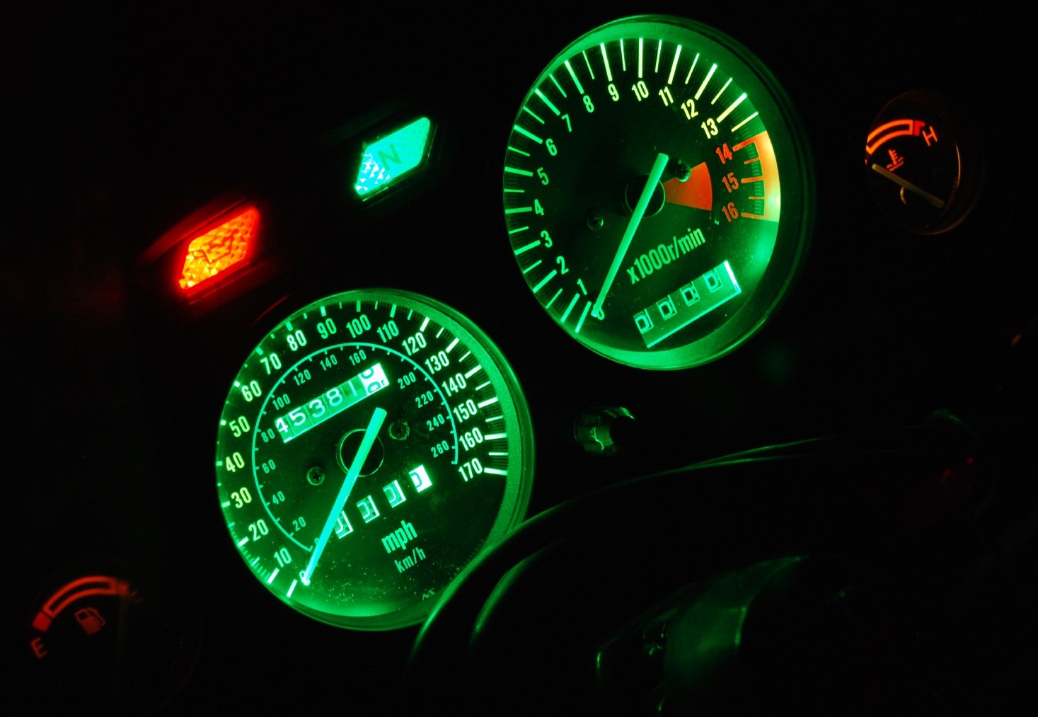
Just did SMD 5050 green LED dash swap! Finally installed ram air tube guards.
 Removed gauge cluster quickly. And then got bogged down with installing the ram air tube guards. They have been missing since I bought the bike and I got these spares from a parts bike awhile back. Had to remove the entire front nose fairing and headlight off the bike to get them in the fit is so tight.
Anyway back to lighting. I bought a single SMD 5050 green LED strip some time back and finally got the time to work on it.
Also got interrupted by phone calls, and having to pick up production gear for a shoot on monday. Grrrr.
Resumed work after moto ride to berkeley be had to re put back in pulled gauges. Driving 60 Mph on fwy with no windscreen at all isn’t as bad as you might think.
I got the tach threaded and then the speedo with a lot of small custom solutions with spare wire and rubber protectors. When I put it all back in, the speedo strip wasnt lighting at all. Took awhile for me to figure to diagnose it with a AC / DC wall wart inside instead of constantly on and off the bike.
I discovered my new soldered wires to the cut factory strip were not working at all.
So Sat am back to work, read about “tinning” the wire and circuit ends first then joining w solder. And that worked great! Now they both light and are much brighter and custom green to boot.
_________________________
Step 1: remove windscreen, and inner gauge plastic dash surround cover, just two screws to remove that part. (Your bike should not look this dirty). 
Step 2: unbolt these two bolts to free up gauges. Do not unbolt upper ones, this whole unit comes out a lot easier with removing the (2) lower 10mm bolts, I’m pointing to left side one.

Detach two electrical leads shown to the gauges, and also the speedo cable that I’m pointing to. The whole thing is now free to lift out.

SMD 5050 strip that I soon cut in half shown also:

So from the backside, locate one of the bulbs that lights up the tach or the one for the speedo and pull out the rubber seal with bulb. You’ll want to tap into the 12V

Next – unscrew the clock faces, just the two little screws so you can have the room you need to wiggle in the SMD strip. I leave the faces loose but don’t remove them.

Here’s the SMD strip wrapped around the tach now. I attached a wire into the bulb holder, passed the wires through the opening and pulled them down to the bottom of gauge area. The black and grey wires are back fed through the stock bulb openings. I wired these extra wires into bulb socket and then attached them to the LED strip leads.

Here’s the wires I fed into the bulb holder, I had some extra car stereo connectors and used that, and then jammed a piece of plastic in between the leads to isolate them from each other. I then stuffed the rubber socket holder back into the back of the gauge cluster to keep it watertight. I can also go back to stock bulbs if I want to this way.

Close up on the speedo and strip tucked behind it.

Here’s the tach plugged in and running!
It’s not too bright at all, just right I am guessing. I don’t think I’d want it any darker so the 5050 SMD extra bright really helps. The super bright green outer circle will be covered up with the gauge plastic cover.
The gauge plastic covering is off and it’s not bolted back in. (I had a problem with the speedo one, apparently my soldering of the cut other half of the strip did not go well). It looked good but won’t pass 12V down it. Hmmm.

Sweet! I just got speedo strip 2 working. I “tinned” the wire first w solder and let it cool and used the factory end of the LED strip where it had been “tinned” at factory and pressed them together and added more solder and voila! Full install pics and nighttime matched exposure picture coming later.
Here’s the installed new dash gauges. The green is a really rich nice green to the eye. Same exposure as first picture. 1/2 second shutter, ISO 400, lens f5.6 , 55mm zoom, I only slightly modified the White Balance to make it a little greener as it looks to the eye.
Comparison to my (crappy) stock old lighting. Note the speedo bulb was in fact burned out, so that upper area would have been a little brighter as stock.

Posted in DIY and tagged gauges, LED, SMD, swap, upgrade, Zx6e, zzr600 by green