ZX10R ’06 rear caliper brake swap!

Mileage: 47,292
Yesterday I just changed out my ’95 stock caliper to a 2006 ZX10R. It’s a direct swap. No mods needed. (Other years of similar era would work too, just check).
Although same lackluster performing caliper they are easier to find, cheap, newer, as quite a few 10 owners upgrade and have them laying around. Had to change pads anyway, and this was almost priced as same price as pads alone.
I bought the entire unit for $40 with about 6K and almost no use (off ex-race champ who never brakes with rear except trail braking). It had been upgraded to steel Galfer line, EBC sintered metallic pads. Came with brake piston cylinder, lines, reservoir, brake lever, clip on, and fluid all still attached with piston freely moving.
Some interesting things happened. Was going to try to swap everything, but found even though the brake cylinder looked identical with same number on front, it has a different part number stamped on the back. And it’s length to the pivot on the foot brake lever is shorter by about 1/2″ or more. I was going to try to use it anyway, figuring it was newer, but I also realized I’d have to mess with the brake light sensor unit and change its length on the collar if I could etc etc…. And at 9pm at night wasnt wanting to make it a longer project. Basically if you just bolted it in as is, the foot brake lever would drop lower, and have less travel to brake, and the brake light would probably be on the whole time unless you adjuster that plastic sensors length (it clearly is adjustable but how far and which direction I did not experiment with after deciding to keep my stock cylinder, upper hose,mand stock upper reservoir.
In fact, the caliper is listed as a different part number but fits no problem. The pads are identical to both ZX6E and ZX10R 2006 era and other years.
The Galfer steel brake line was quite long, and I had to flip over both banjo bolt ends
As they seemed to be angled wrong.
The upper reservoir looked the same, but looking closer the feeder at bottom was in reverse position, and then I noticed it had upper and lower markings on both sides! So although its different Kawi probably had it doing double duty in multiple bikes. The brake hoses are wider gauge on the E stock unit all around compared to the ZX10R.
So in summary, easy caliper and pad swap out, no problem at all. Everything interchanges and mixes and matches perfectly. Brake works great now too! Lots of bite in back now.
Lines and banjo bolts all match and bolt threads etc…
The ZX10 brake cylinder could I feel be used – it has identical bolt in position and pattern to footpeg brackets. But you’d probably have to lengthen the pivot bolt by loosening the nuts and extending the pivot down (I did that in fact but stopped the install due to other reasons.)
The upper reservoir could be used with zx10R hoses to cylinder if all off same bike, but you would probably either have to mount it backwards up top, and have the angle of the outlet at bottom pointing slightly the wrong way or better yet just make a metal extension piece to keep the reservoir facing the way the E wants it, it would be like a 3 or 4 inch piece with a mount spot.
ZX10R complete setup as purchased in pic below.

Original stock unit before replacement. Pads totally shot.

Posted in DIY and tagged caliper, rear brake, upgrade, ZX10R, Zx6e, zzr600 by green
“The Duct Tape Method” DIY change tires motorcycle yourself without tools! How to
I double taped about 2-3 inches or so on about 16″ strips. So lay out long strip and cut a short piece and tape over it so the two sticky parts lay face together stuck together. Why? That’s the part you line up with the tire inner bead part. This way you can pull it out easily and fast after tire put on.
CLICK pic below to see my video here:
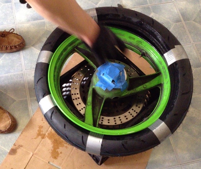
I taped the sticky long half under tire pressed two walls together – which is SUPER easy with the Q3. Mine was soft as butter after spending about 6 hours inside a normal temp apt. Did it with a finger and a thumb it’s so compliant.
Space those tape points roughly out the same. Then I used just a little dish soap and water mix around the tire and wheel half where I’d have to push.

I got it about 65% on and it started getting very tight. This is where I said in my head “there is no f-ing way this is gonna happen” But I made sure the already mounted portion was snug squarely in the center of the wheel and therefore its smallest radius. In fact I kind of man handled it pretty good and stuffed it and made sure it was snug in there. That made a big difference – even though it looked the same before, it wasnt. Smoosh that tire up in there inside that middle part of the rim!
Then I pushed on both sides of last 35% of tire and in about 30 seconds it just plop! Slid right over the wheel rim!
I was shocked that worked. Aired up a gas station to about 70 psi and got 95% of bead perfect in. 2nd to last bead I had to bounce a lot and more air to 70 and it POPPED in loud. Didn’t want to go higher air pressure and bounced it a lot, finally tossed in my car trunk with one last part not fully seated – although holding air just fine for now. About 25 minutes later it had seated itself perfectly. Aired down to 40 lbs and voila! New tire!
(The old tire I chopped up a lot before breaking the bead – not good. Not recommended, break bead fully first! Although by slicing through one entire sidewall and having 2 separate parts I was able to dismount the tire with my bare hands and not much force. This is coming from the guy who can hardly center stand this bike so I’m not the most ripped person on earth I’ll tell you that! Think computer user body build). No irons no spoons NO rim damage!
Finally broke both beads on the front tire. Was at it 1-2 hrs. So before I forget, I’ll post tips.
I borrowed two craftsman bar clamps with the squeezy grips. Another C clamp style one was worthless. These two is what I needed. The 8″ wooden angle changing one that Pengaru has in the tire change DIY sticky would be a lot better.
Set both clamps about 4-6″ apart on wheel. I tried and tried and tried. Was about to give up. And I recalled how I chopped through rear tire. 
So I sawed horizontal cut through front tire, and was able to push in tire. And I coated inside it up a lot with water and soap and that’s what finally enabled me to break it free, lubing inside bead and tire area. If you have trouble with clamps do that and it will help a lot.
I didn’t have an easy ability to make the wooden 2×4′ eight foot lever using a car thing, next time I’d prefer to try that or get the wooden clamp. This method was a lot of grief.
(I couldn’t push this one off like the rear, wasn’t even close to going. Tried clamping sidewalls together and that’s closer but not close enough.)
Wow, getting old tire off and new on was easy! Not really harder than rear wheel.
I used DUCT TAPE again to get old tire off and new one on. No extra cutting.
Now just need to air up

Edit: I put the f ing tire on the wrong direction this time. I was so pissed.
I just had to completely redo it BUT it did go smooth once re duct taped it again AND I shot a video of it this time. Should not have forgotten to check direction. But at least its on and right direction.
I’ve just slipped both sides together off the rim with duct tape. A milk crate underneath works great for protection.
(I did remove the right rotor but don’t real need to if you’re careful. Next change I won’t bother).
This is how I duct taped the tire beads together to slide it off the rim (didn’t take a ‘before’ pic).
I did actually use a small zip tie to fish the first piece of duct tape between rim and tire. After first tape piece is in its much easier with more space to work. Notice hacksaw cut for applying inner lubricant for breaking the bead step earlier.

The brand new tire all taped up and ready to try installing. This was my first attempt on a front wheel ever and it went on a lot easier than I thought. I recommend duct tape because its a wider band and will potentially cut less into new tire than a zip tie, not scratch rims like a lever could and most people actually have duct tape on hand!

I made my own little wheel balance station like this below. I leveled (with a level) side to side and front to back two milk crates on a small table and then used the actual axle to mount the wheel and spin the wheel. It’s more like you try to find the heavy spot, and raise it from the bottom up 90 degrees to a 9 or 3 O’clock type position (horizontal heavy part on wheel down), and let it fall. Keep adding weight until is does not spin down at all. I used very strong magnets for this to the rim, adding 1 at a time.

I wound up being 1.3 oz out of balance on the rear wheel, and fine on the front wheel and made no adjustments there. About a month and, um 1200 miles later, finally got peel and stick wheel weights and installed 1.3 oz on rear wheel where I had marked it with tape.
Posted in DIY, repair and tagged change tires, duct tape method, no tools, Zx6e, zzr600 by green
Just did SMD 5050 green LED dash swap! Finally installed ram air tube guards.
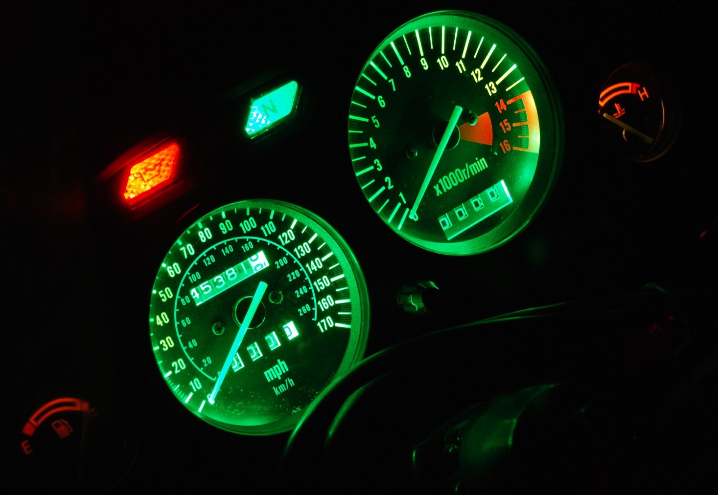 Removed gauge cluster quickly. And then got bogged down with installing the ram air tube guards. They have been missing since I bought the bike and I got these spares from a parts bike awhile back. Had to remove the entire front nose fairing and headlight off the bike to get them in the fit is so tight.
Anyway back to lighting. I bought a single SMD 5050 green LED strip some time back and finally got the time to work on it.
Also got interrupted by phone calls, and having to pick up production gear for a shoot on monday. Grrrr.
Resumed work after moto ride to berkeley be had to re put back in pulled gauges. Driving 60 Mph on fwy with no windscreen at all isn’t as bad as you might think.
I got the tach threaded and then the speedo with a lot of small custom solutions with spare wire and rubber protectors. When I put it all back in, the speedo strip wasnt lighting at all. Took awhile for me to figure to diagnose it with a AC / DC wall wart inside instead of constantly on and off the bike.
I discovered my new soldered wires to the cut factory strip were not working at all.
So Sat am back to work, read about “tinning” the wire and circuit ends first then joining w solder. And that worked great! Now they both light and are much brighter and custom green to boot.
_________________________
Step 1: remove windscreen, and inner gauge plastic dash surround cover, just two screws to remove that part. (Your bike should not look this dirty). 
Step 2: unbolt these two bolts to free up gauges. Do not unbolt upper ones, this whole unit comes out a lot easier with removing the (2) lower 10mm bolts, I’m pointing to left side one.

Detach two electrical leads shown to the gauges, and also the speedo cable that I’m pointing to. The whole thing is now free to lift out.

SMD 5050 strip that I soon cut in half shown also:

So from the backside, locate one of the bulbs that lights up the tach or the one for the speedo and pull out the rubber seal with bulb. You’ll want to tap into the 12V

Next – unscrew the clock faces, just the two little screws so you can have the room you need to wiggle in the SMD strip. I leave the faces loose but don’t remove them.

Here’s the SMD strip wrapped around the tach now. I attached a wire into the bulb holder, passed the wires through the opening and pulled them down to the bottom of gauge area. The black and grey wires are back fed through the stock bulb openings. I wired these extra wires into bulb socket and then attached them to the LED strip leads.

Here’s the wires I fed into the bulb holder, I had some extra car stereo connectors and used that, and then jammed a piece of plastic in between the leads to isolate them from each other. I then stuffed the rubber socket holder back into the back of the gauge cluster to keep it watertight. I can also go back to stock bulbs if I want to this way.

Close up on the speedo and strip tucked behind it.

Here’s the tach plugged in and running!
It’s not too bright at all, just right I am guessing. I don’t think I’d want it any darker so the 5050 SMD extra bright really helps. The super bright green outer circle will be covered up with the gauge plastic cover.
The gauge plastic covering is off and it’s not bolted back in. (I had a problem with the speedo one, apparently my soldering of the cut other half of the strip did not go well). It looked good but won’t pass 12V down it. Hmmm.

Sweet! I just got speedo strip 2 working. I “tinned” the wire first w solder and let it cool and used the factory end of the LED strip where it had been “tinned” at factory and pressed them together and added more solder and voila! Full install pics and nighttime matched exposure picture coming later.
Here’s the installed new dash gauges. The green is a really rich nice green to the eye. Same exposure as first picture. 1/2 second shutter, ISO 400, lens f5.6 , 55mm zoom, I only slightly modified the White Balance to make it a little greener as it looks to the eye.
Comparison to my (crappy) stock old lighting. Note the speedo bulb was in fact burned out, so that upper area would have been a little brighter as stock.

Posted in DIY and tagged gauges, LED, SMD, swap, upgrade, Zx6e, zzr600 by green
DIY waterpump rebuild (proper thread). Published from old zzr-international.co.uk site by dirtdoggle
DIY waterpump rebuild (proper thread)
Postby dirtdoogle » Tue Aug 21, 2012 11:43 am
I apologise in advance for my poor pics, nerve damage in my right wrist makes me shake a wee bit 😉
What you need:
A ZZR4/600/K/D, haven’t done one on the N/E but I think they’re the same
10 and 8mm spanners
Many hammers
Cigarettes
Socket set
Assortment of decent screw drivers
Circlip pliers
Extensive knowledge of grunting and swearing
Bearing puller really, really helps
Parts: Loctite sealant or similar
A wee bit of grease (if pedantic like myself)
Bearings: Two 12x28x8 stainless steel and must be 2RS sealed type (these cost me a grand total of $5NZ)
12 x 28 x 7mm radius oil seal
12mm external circlip
Rear water pump o-ring http://www.ronayers.com/ProductDetails/ … KU/1088282
Front water pump housing seal http://www.ronayers.com/ProductDetails/ … KU/1088281
Righto what you want to do:
Remove your bottom fairing (no pics, my bike obviously hasn’t got one, fairings are silly)
Drain the coolant, if unsure of how to do this, step away from the bike and go have a coffee.
Remove both hoses to the water pump
Un do the top and bottom 10mm bolts on the front of the pump
Ease the pump out
Now the fun begins.
Remove the remaining bolts from the pump cover and open ‘er up
Should look like this, hopefully…
Image
Now flip it over so you’re looking at the back
In theory, you’ll be looking at an oil seal
Image
Pop this wee fellow out and you’ll be able to see a circlip on the shaft holding the bearing in
Whip that out with the previously mentioned circlip pliers (or get real handy with a flat blade screw driver…)
Now you can grab you hammer assortment! Yay!
Place the pump on blocks of wood, impeller facing down and make sure it’s not hitting the wood
Gently drive the pump shaft out, this may require the grunting and/or swearing you got yourslef before starting this job.
Once you’ve managed to get the impeller and shaft out, flip it over and you should see this
Image
I didn’t need to replace this seal on mine, but do note how it sits on yours (this seal causes a lot of drag, I’m currently trying to think of a mod to get rid of it)
Ease it off and you’ll see this
Image
If not, you’ve started working on the wrong bike and it’s not my problem
Now, select your favourite long screw driver (unless you have a bearing puller, then you win) and drive the bearing on the engine side out, heat can help here, I’m a sucker for making shit hot, so I put it in the oven for half an hour at 150 celcius, made life superbly easy!
Once that bearing is out, flip the pump, burn your hands (oops!) and gently tap the other side out, I used a socket and wooden mallet for this one and being heated, they popped right out (the pump I did before hand wasn’t heated and was a prick to do)
Now you’ll have a completely empty water pump! The end.
No not really…
I’m sorry for the lack of pictures, most of the ones I took are too blurry to make sense 😆
Clean everything, I cannot stress this enough, if you’re spending time doing something like this, make it perfect
Is it clean yet?
Good.
Insert the new impeller side bearing and gently drive it in, makes life easier yet again if the pump is a bit warm, and I always put bearing in the freezer before installation, easier than peeling a potato with a gun.
It should look like this Image
If not, you’re a womble and should stop sniffing glue
Clean this wee thingy Image I used brake cleaner and a razor blade, but I’m slightly pedantic.
Apply a very thin smear of the loctite sealant stuff, or whatever is on hand (blood, feces etc)
It’ll push right in if you freeze it… otherwise, get a socket (I think 16mm was about right) and very gently tap it in
Once that’s nice and snug, fit that odd little spring loaded washer/seal, making sure it’s alligned correctly on the little dimples.
I think fitting a teflon washer between that and the impeller will get rid of the ridiculous drag it causes
Now, find the impeller, put a thin smear of grease on it and push it through (yet again, heat/cold parts help, but hammers work too)
Once you have that in, insert the new bearing in the engine side, double check that the impeller has clearance on the housing too, otherwise you’ll have a big mess
Fit the circlip
Apply a tiny smear of the sealant rubbish on the outside of that new oil seal and push it firmly in to place.
Don’t forget that new rear O-ring!
Flip it over again, check you’ve still got clearance on the impeller
Mount the housing on the motor and turn the impeller until you feel the shaft slip in to place of it’s drive
Clean the mating surfaces on the housing, fit new seal (or just use more sealant, not my problem)
Fit the from cover and bolt ‘er up
Polished front is optional and not worth doing on a faired bike
Image
I hope this helps someone, it’s long stupid and rambling, but you’ve made it this far and good luck to you
Will update once I have found a decent alternative to the inside seal 🙂
———-
Green Magic Man (me) add this to the post:
I thought I should pass along this research. An Italian at the German zzr site said he did his ZZR600 D model water pump with this Honda part which is the same seal for the oil seal in the Kawi.
Part # 91201-mf2-003
I looked it up and it shows up indeed as:
Honda 91201-MF2-003 OIL SEAL (12X28X7) — OIL SEAL ( 12X28X7) (Honda Code 2073054), OIL SEAL …
For US $3.50 at partzilla, US $4.50 at local Kawi dealer.
I will order one and try to confirm this fits in my ZZR600 water pump. I think that enables me to source all the parts at this point.
This was the post:
http://www.zzr-rg.co.uk/forum/viewtopic.php?t=5163
Also, cross referenced another part, this one is a Kawasaki part a forum poster says fits too:
92049 1416 said this fits but is not common knowledge it fits most Kawasakis.
And same guys says this for the mechanical seal part: 49063 1055
Here is my source thread for this: http://www.kiwibiker.co.nz/forums/showt … -weep-hole
—
I can indeed confirm this Honda oil seal part fits the ZX6E / ZZR600 model :clap: :
Honda part #: 91201-MF2-003
description: OIL SEAL (12X28X7)
price: US Dollars $4.99
I had to special order the part and installed it today. Very nice fit. This is the oil seal that goes around the impeller shaft at the very end (not the wider O Ring that goes around the water pump impeller housing.
Posted in DIY, repair and tagged DIY, how to, Kawasaki, rebuild, water pump, Zx6e, zzr-international.co.uk, zzr600 by green